
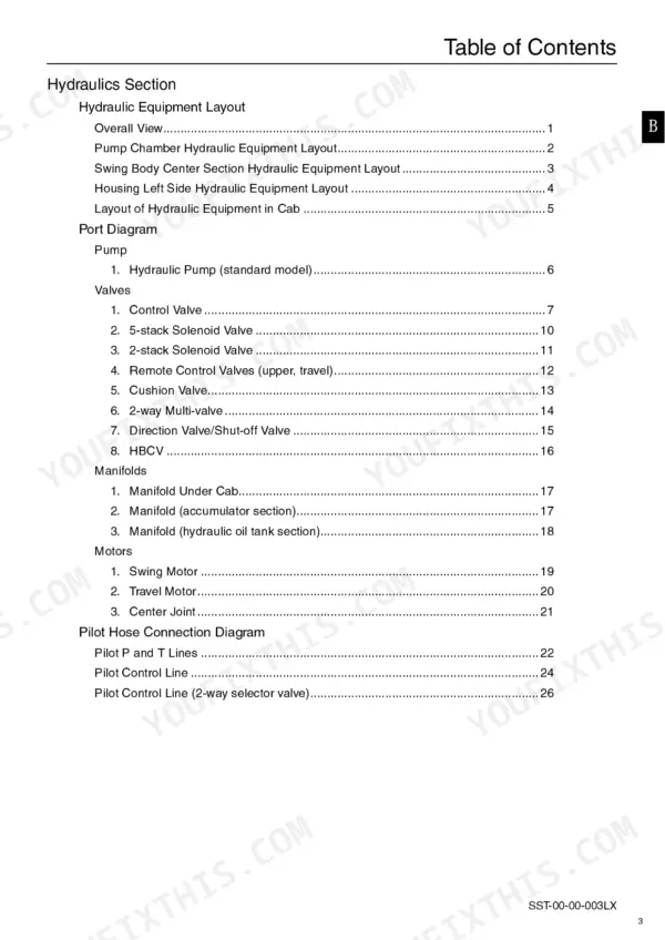

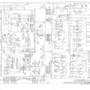
A pilot circuit that will not build pressure and a 290X2 sitting dead while the crew stands around: that is the job this book answers. This Link-Belt 290X2 service manual PDF packs 835 pages of factory hydraulic, electrical, and engine coverage for the hydraulic excavator. Wiring diagrams trace every harness from main frame through cab and console, and hydraulic schematics follow each circuit, from travel and swing through boom-down regeneration and arm-in load hold. Diagnostic trouble code tables and the service support screens show you how to read faults straight off the monitor. Set the main relief at 4975 PSI (34.3 MPa) and confirm supply voltage holds between 20 and 32 volts before condemning the computer. When it is just you and a quiet machine at the far corner of the site, the bookmarked, text-searchable file answers back. Download it and read the circuit before you crack a fitting.
What's Inside This Link-Belt 290X2 Manual
| System | Pages | Key Topics |
|---|---|---|
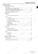
| Specifications, Main Equipment and Hydraulic Layout | 1-12 | Main Data, Performance, Main Body Dimensions, Engine, Cooling System, Swing Units, Travel Lower Body, Hydraulic Equipment Layout |
| Work Range Diagrams and Function Tables | 13-35 | Standard Arm, Short Arm, Long Arm, Travel Circuits, Swing Circuits, Boom and Arm Circuits |
| Explanation of Hydraulic Circuit and Operation | 36-103 | Travel Low and High Speed Circuits, Swing Relief Cut Control, Negative Control Power Save, Breaker and Option Circuits |
| Main Equipment Structure, Electrical Layout and Options | 104-121 | Pump, Gear Pump, Travel Motor, Connector Pin Layout, Option Line Control |
| Hydraulic Circuit Diagrams and Component Structure | 122-249 | Circuit Schematics, Manifolds, Structural Diagrams, Load Hold Valve Circuits |
| Explanation of New Functions | 250-343 | External Switch Input Ports, Work Mode Select, Serial Communication to Monitor, Service Support Screens |
| Explanation of Functions and Operations | 344-505 | Gauge Level and Lever Angle, Fuel Sensor Processing, Message Display List, Trouble Mode Handling |
| Troubleshooting and Actuator Checks | 506-599 | Actuator Operation Checks, Diagnostic Sequences, Electrical Fault Tracing |
| Maintenance: Electric Equipment Checking Procedure | 600-602 | Electrical Checks, Measuring Procedures |
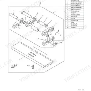
| Lower Mechanism: Track Shoe and Travel Drive Unit | 603-677 | Track Shoe, Travel Drive Unit, Disassembly and Reassembly, Maintenance Standards |
| Upper Swing Body: Pump | 678-723 | Pump Disassembly, Reassembly, Adjustment, Maintenance Standards |
| Upper Swing Body: Remote Control Valve | 724-766 | Valve Structure, Disassembly, Reassembly |
| Upper Swing Body: Control Valve | 767-774 | Control Valve Structure, Spool Servicing |
| Upper Swing Body: Solenoid Valve | 775-789 | Solenoid Valve Servicing, Testing |
| Upper Swing Body: Tank and Related Equipment | 790-803 | Hydraulic Tank, Fuel Tank, Filters |
| Cab Inner and Outer Parts: Removal and Installation | 804-824 | Cab Removal, Interior Trim, Reinstallation |
| Hydraulic Equipment | 825-835 | Hydraulic Equipment Servicing, Final Checks |
Quick Reference Specifications
| Specification | Value | Page |
|---|---|---|
| Set pressure of main relief valve | 4975 PSI (34.3 MPa) | p. 109 |
| Set pressure of overload relief valve (boom down) | 4264 PSI (29.4 MPa) | p. 109 |
| Main pump operating pressure (Rated) | 4974.8 PSI (34.3 MPa) | p. 46 |
| Main pump operating pressure (Maximum) | 5409.8 PSI (37.3 MPa) | p. 46 |
| Operating voltage | 20 to 32 V | p. 52 |
| Power consumption | 17 W | p. 52 |
| Fuel sensor lever angle (Gauge level 7) | 88.3% | p. 345 |
| Fuel sensor lever angle (Gauge level 6) | 81.0% | p. 345 |
| Hydraulic pump bolt tightening torque | 47.2 to 54.6 lbf·ft (64 to 74 N·m) | p. 584 |
| Hydraulic pump (M20) bolt tightening torque | 270.7 to 365.8 lbf·ft (367 to 496 N·m) | p. 584 |
| Suction filter replacement interval | 5000 hours | p. 827 |
| Fuel capacity | 118.9 Gal. (450 L) | p. 30 |
Link-Belt 290X2 Common Problems This Manual Covers
Link-Belt 290X2 throws code 0087, no pumping pressure, boom and arm dead
Check main relief pressure at the control valve; it should reach 4974.8 PSI (34.3 MPa) per the spec on page 48. If pressure will not build, test pilot pump output against the 568.5 PSI (3.92 MPa) spec on page 46, then inspect the pump rotating group before condemning the pump.
Manual Section: Explanation of Hydraulic Circuit and Operations (Standard Model) p. 48Travel motor weak on one side, track drags, abnormal noise from final drive
Measure travel motor case drain volume at 370 PSI (2.55 MPa) as listed on page 103; heavy drain flow means a worn rotating group. Check parking brake torque against the 902 N-m criteria on page 646, and replace friction plates if total stack thickness measures under 21.7 mm.
Manual Section: Hydraulic motor troubleshooting p. 646Code 0219 limit operation active, machine derates, digging power drops under load
Pull the stored codes and match them against the error code reference. Test each flagged pressure sensor circuit; supply voltage must sit inside the DC 20 to 32 V operating range shown on page 52. Repair harness faults using the wiring diagram before swapping sensors.
Manual Section: Main Unit Diagnostic Trouble Code ListJoystick response sluggish, boom and swing hesitate, pilot pressure reads low at idle
Test pilot pump output; spec is 568.5 PSI (3.92 MPa) at 7.1 Gal. (27 L)/min and 1800 min-1 per page 46. If secondary pressure stays low or unstable, inspect the remote control valve spools and springs for sticking, then confirm the pilot circuit strainer is clean.
Manual Section: Remote Control Valve Troubleshooting p. 46Main pump whines on high-hour machine, cycle times slow, hydraulic oil runs hot
Inspect the pump rotating group; piston to cylinder bore clearance for the K3V112 must not exceed 0.067 mm per the wear table on page 692. Replace the suction filter at the 5000 hour interval listed on page 827, then torque pump mounting bolts to 47.2 to 54.6 lbf-ft (64 to 74 N-m).
Manual Section: Service Support p. 692Frequently Asked Questions
How do you reset the trouble log on a Link-Belt 290X2?
To reset the trouble log, hold down the washer switch and the light switch simultaneously for 10 seconds while in the diagnosis mode. This action will clear the recorded trouble log. p. 384
What is the tightening torque for the M18 x 100 hexagon socket head bolts on the travel drive unit?
The tightening torque for the M18 x 100 hexagon socket head bolts used on the travel drive unit is 378±38 N-m. p. 668
What is the standard engine oil replacement interval for the Link-Belt 290X2?
The engine oil and engine oil filter element should be replaced every 250 hours of use. p. 476
What is the correct procedure for bleeding air from the hydraulic pump?
To bleed the hydraulic pump, loosen the air bleed plug to check for oil flow. If no oil flows, remove the plug and fill the pump case with hydraulic oil through the port, then temporarily tighten the plug. Run the engine at low idle, slightly loosen the plug again until oil oozes out, and then fully tighten it. p. 552
What is the specified fuel for the Link-Belt 290X2 engine?
The engine requires diesel fuel with a sulfur content of 2500 ppm or less and an HFRR (High-Frequency Reciprocating Rig) value of 18.1 in. (460 mm) or less. p. 475
What format is this Link-Belt 290X2 manual in?
A single searchable PDF file of 835 pages, downloadable right after payment. Nothing ships, nothing waits in the mail.
Can I print this Link-Belt 290X2 manual?
Yes. Print the sections you need to take out to the shop for your own use. Standard letter or A4 paper works.


Reviews
There are no reviews yet.