
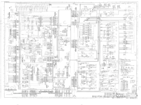
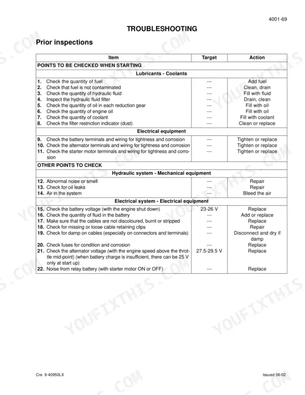
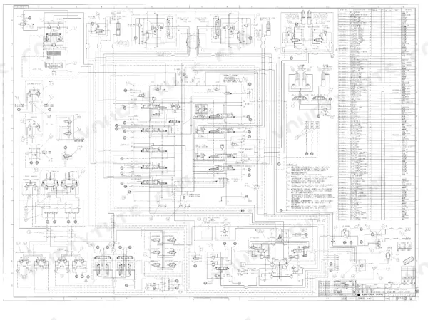
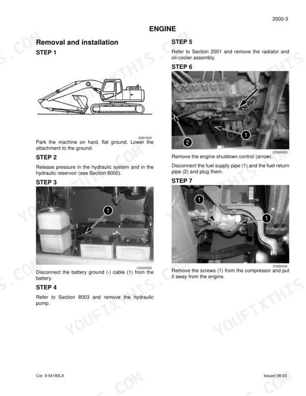
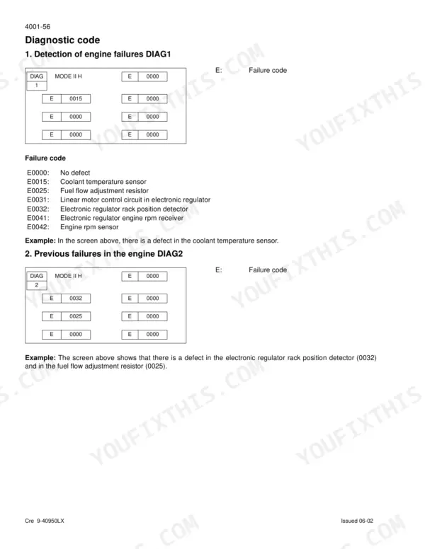
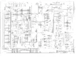
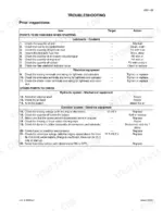
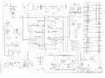
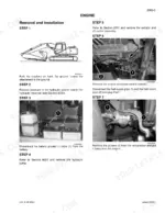
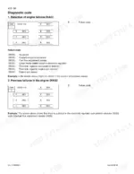

Book No. Cre 9-54350LX is the factory publication for the Link-Belt 460LX crawler excavator, and this Link-Belt 460LX service manual PDF reproduces all 589 pages of it. Electrical and electronic troubleshooting takes up the largest single block of the book, tracing faults through the main and engine electronic control boxes, while the large-format hydraulic and electrical schematics from the back pocket appear at full size. Hydraulic coverage runs from pressure settings and travel drift diagnosis down to teardown of the main control valve, swing motor, and attachment cylinders. Check main pump output against the rated 2 x 95 gpm, and condemn a swing motor once case leakage passes 4.7 gpm. Guess wrong on figures like those and you buy the part twice and pay for the teardown twice. Bookmarked, with a real text layer for keyword lookups, this file is yours to keep for the life of the machine.
What's Inside This Link-Belt 460LX Manual
| System | Pages | Key Topics |
|---|---|---|
| General Information | 5-36 | Safety, Standard Torque Data |
| Engine | 37-48 | Removal and Installation of the Engine, Radiator and Oil-Cooler, Engine Specifications, Disassembly and Assembly of the Engine |
| Fuel System | 49-54 | Fuel Tank, Fuel Engine System |
| Electrical System | 55-160 | Electrical and Electronic Troubleshooting, Maintenance of Batteries and Connecting a Booster Battery, Main and Engine Electronic Control Boxes |
| Undercarriage | 161-214 | Removal and Installation of Tracks, Rollers, Sprocket, Idler Wheel and Tension Shock Absorber |
| Drive Train | 215-238 | Drive Motor and Final Drive Transmission Removal and Installation, Swing Reduction Gear, Removal and Installation, Disassembly and Assembly |
| Undercarriage Hydraulics | 239-252 | Travel Reduction Gear |
| Pressure Release, Decontamination, and Vacuum Pump | 253-262 | Hydraulic Pressure Release, Hydraulic System Decontamination, Vacuum Pump Installation, Bleeding Air From Components |
| Hydraulic Specifications, Troubleshooting, and Inspections | 263-290 | Hydraulic Pressure Settings, Travel Drift Troubleshooting, Swing Motor Leak Checks, Pilot System Relief |
| Hydraulic Reservoir and Main/Pilot Pumps | 291-306 | Hydraulic Reservoir Removal, Main Hydraulic Pump Removal, Pilot Pump Installation, Hydraulic Pump Coupling |
| Main Hydraulic Control Valve | 307-392 | Control Valve Removal, Control Valve Disassembly, Anti-Drift Check Valve, Spool Assembly |
| Attachment Cylinders | 393-444 | Boom Cylinder Disassembly, Dipper Cylinder Removal, Bucket Cylinder Assembly, Cylinder Seal Replacement |
| Solenoid Valves and Control Levers | 445-540 | Six Solenoid Valve Block, Cushion Control Valve, Control Lever Disassembly, Control Pedal Maintenance |
| Upperstructure | 541-589 | Turntable and Counterweight, Boom, Dipper and Bucket, Seat and Seat Belt, Cab and Cab Equipment, Air Conditioning Troubleshooting, Air Conditioning Unit Disassembly and Assembly |
Quick Reference Specifications
| Specification | Value | Page |
|---|---|---|
| Swing motor permissible motor leak | 4.7 gpm | p. 21 |
| Travel motor permissible motor leak | 3.7 gpm | p. 21 |
| Main hydraulic pump maximum flow | 2 x 95 gpm | p. 21 |
| Hydraulic pilot pump maximum flow | 8 gpm | p. 21 |
| Upper roller diameter (standard) | 5.9 in | p. 25 |
| Lower roller diameter (standard) | 7.87 in | p. 26 |
| Idler wheel diameter (standard) | 26.6 in | p. 24 |
| Travel motor and reduction gear assembly torque setting | 664-774 lb-ft | p. 33 |
| Swing motor and reduction gear assembly torque setting | 664-774 lb-ft | p. 33 |
| Idler wheel torque setting | 197-230 lb-ft | p. 33 |
| Engine Oil Capacity | 8.7 gallons | p. 19 |
| Hydraulic Fluid Reservoir Capacity | 58 gallons | p. 19 |
Link-Belt 460LX Common Problems This Manual Covers
Link-Belt 460LX tracks loose and jumping the idler, undercarriage rollers squealing on rough ground
Check track tension using the adjustment procedure in the Undercarriage section starting on page 161. Measure the idler wheel: standard diameter is 26.6 in per page 24, and lower rollers should measure 7.87 in per page 26. Replace worn wheels, then torque idler mounting bolts to 197-230 lb-ft per the chart on page 33.
Manual Section: Undercarriage p. 161Machine tracks crooked on level ground, one side travels noticeably slower under load
Run the travel drift checks starting on page 263 with the machine on level ground. Measure each travel motor case drain flow; anything over the 3.7 gpm permissible leak listed on page 21 means the motor is worn out. When reinstalling a motor and reduction gear assembly, torque the M24 mounting screws to 664-774 lb-ft per page 33.
Manual Section: Hydraulic Specifications, Troubleshooting, and Inspections p. 263Swing sluggish and upperstructure creeps on slopes even with swing brake applied
Test swing motor leakage using the inspection procedure starting on page 263. Measure case drain flow while swinging against relief; anything over the 4.7 gpm permissible leak on page 21 calls for motor repair or replacement. Torque the swing motor and reduction gear mounting screws to 664-774 lb-ft per the torque chart on page 33.
Manual Section: Hydraulic Specifications, Troubleshooting, and Inspections p. 263All hydraulic functions slow and weak at full throttle, boom struggles to lift loaded bucket
Verify main circuit relief pressure against the 4554 ± 43 psi standard and 4975 ± 72 psi power-up settings listed on page 20; test and adjustment procedures start on page 263. Check reservoir level first, the tank holds 58 gallons. If pressure tests low on both circuits, inspect the main pump, covered starting on page 291.
Manual Section: Hydraulic Specifications, Troubleshooting, and Inspections p. 263Boom drifts down overnight and cylinder rod seals weep oil around the gland
Release hydraulic pressure using the procedure starting on page 253 before opening any circuit. Inspect the boom cylinder rod and gland seals; reseal procedures begin on page 393, and the bore measures 6.7 in per the specs on page 20. Test the anti-drift check valve in the main control valve, covered starting on page 307.
Manual Section: Attachment Cylinders p. 393Frequently Asked Questions
How do you reset a Link-Belt 460LX fault code?
To erase diagnostic data, press the work mode switch for a minimum of 10 seconds until the audible warning device sounds. This procedure applies to screens DIAG2, DIAG3, DIAG5, and DIAG6. p. 106
What are the torque specifications for the Link-Belt 460LX track pad bolts?
The torque specification for the track pad bolts (M24 screw) is 912-1114 lb-ft. p. 33
How do you clear a shutdown on a Link-Belt 460LX?
If the engine emergency stop switch (S9) is activated, the status is maintained even after the ignition is switched off. To deactivate the emergency stop, the engine emergency stop switch (S9) must be pressed once again, and the LED will go off. p. 86
What is the engine oil capacity for the Link-Belt 460LX?
The engine oil capacity for the 460LX is 8.7 gallons. p. 19
What is the torque specification for the main hydraulic pump retaining screws?
The main hydraulic pump retaining screws have two torque specifications depending on the screw size: 47-54 lb-ft for M10 screws and 270-366 lb-ft for M20 screws. p. 33
What do I get after purchasing this Link-Belt 460LX manual?
You download the Service Manual yourself: 589 pages, searchable PDF, available immediately. Keep a copy on every device you use.
Am I free to print this Link-Belt 460LX Service Manual?
Yes. Printing works from any reader and any printer, for your own shop use.



Reviews
There are no reviews yet.