
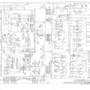
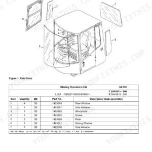
Before the end of the shift you could be setting track tension to the factory figure with the Link-Belt 160LX service manual PDF open beside the machine: 621 pages, OEM book number 1031, covering the crawler excavator from undercarriage to counterweight. Wiring diagrams trace the electrical system down to component locations and the electronic control boxes, and hydraulic schematics map the pilot circuit, main control valve, and swing motor. Troubleshooting tables walk travel drift, swing brake, and cushion control faults back to pressure settings you can verify at the port. Set track sag between 10.24 and 11 inches, then torque the M20 pad bolts to 55-62 lb-ft. Every hour this excavator sits, a crew stands around it. Download the bookmarked, text-searchable PDF and get the tracks turning again.
What's Inside This Link-Belt 160LX Manual
| System | Pages | Key Topics |
|---|---|---|
| General Information | 5-36 | Safety, Standard Torque Data |
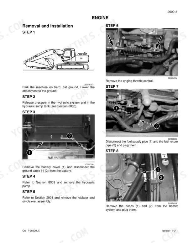
| Engine | 37-48 | Removal and Installation, Radiator and Oil-Cooler |
| Fuel System | 49-54 | Fuel Tank Removal and Installation |
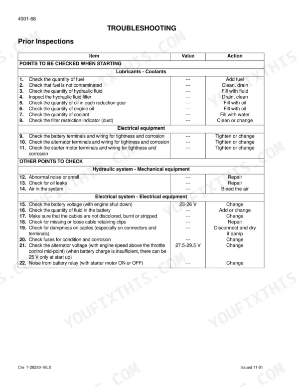
| Electrical System | 55-144 | Location of Components, Basic Operating Principles, Troubleshooting |
| Undercarriage | 145-198 | Removal and Installation of Tracks, Upper and Lower Rollers, Sprocket Removal and Installation, Idler Wheel and Shock Absorber |
| Drive Train | 199-262 | Drive Motor and Final Drive Transmission Removal and Installation, Drive Motor and Final Drive Transmission Disassembly and Assembly, Swing Reduction Gear, Removal and Installation |
| Hydraulic System Maintenance and Bleeding | 263-272 | Depressurizing, Decontamination, Vacuum Pump, Bleeding Components |
| Hydraulic Specifications and Troubleshooting | 273-300 | Pressure Settings, Troubleshooting, Travel Drift, Swing Brake, Cushion Control |
| Hydraulic Sump Tank and Main Pump | 301-374 | Sump Tank Removal, Main Hydraulic Pump, Pilot Pump, Pump Coupling |
| Control Valves and Pilot Function Blocks | 375-472 | Main Control Valve, Pilot Function Blocks, Hand Joystick Control, Travel Pedal Control |
| Attachment Cylinders and Valves | 473-564 | Attachment Cylinders, Hose Burst Check Valve, Cushion Control Valve, Six Stack Solenoid Valve |
| Upperstructure | 565-621 | Turntable and Counterweight, Boom, Arm and Bucket, Seat and Safety Belt, Cab and Cab Equipment, Air Conditioning Troubleshooting, Air Conditioning Unit Disassembly and Assembly |
Quick Reference Specifications
| Specification | Value | Page |
|---|---|---|
| Ground pressure with 19.68 in track pads | 6.8 psi | p. 21 |
| Ground pressure with 23.6 in track pads | 5.66 psi | p. 21 |
| Thermostat opening range (starts to open) | 180°F (82°C) | p. 44 |
| Thermostat opening range (completely opened) | 203°F (95°C) | p. 44 |
| Fuel level sender resistor | 10.0 - 80.0 Ω | p. 101 |
| Torque spanner | 700 Nm | p. 159 |
| Oil level, fill plug and oil drain plug torque | 3.6 to 8 lb-ft (5 to 11 Nm) | p. 200 |
| Main relief valve (standard pressure) P2 | 4975±45 psi | p. 286 |
| Main relief valve (higher pressure - 2-stage relief) P2 | 5265±70 psi | p. 286 |
| Screw for fixing the main pump to the coupling flange | 70 to 89 lb-ft (88 to 111 Nm) | p. 361 |
| Screw for fixing the grooved spacer to the coupling assembly | 152 to 167 lb-ft (206 to 226 Nm) | p. 361 |
| Boom cylinder Hydraulic pipes retaining screws (4) | 38 lb-ft (51 Nm) | p. 475 |
Link-Belt 160LX Common Problems This Manual Covers
Link-Belt 160LX intermittent warning light and electrical fault that clears after shutdown and restart
Check for code E0025 before condemning parts. Work the diagnostic code procedures starting, wiggle-testing the harness and connectors at the fuel injection pump resistor circuit while watching for the code to reset. Test the fuel level sender per page 101; resistance outside 10.0 to 80.0 ohms means a failed sender, not the resistor.
Manual Section: Electrical SystemHydraulic hose bursts under load shortly after a replacement hose was installed
Verify the replacement hose carries the OEM pressure rating before hanging another one. Test main relief pressure against the 4975±45 psi setting on page 286; a stuck relief valve overpressures every line downstream and will keep eating hoses. Torque boom cylinder pipe retaining screws to 38 lb-ft (51 Nm) per page 475 when reconnecting.
Manual Section: Hydraulic Specifications and Troubleshooting p. 286Track keeps coming loose, clacking over the sprocket, or throwing off on uneven ground
Measure track sag and adjust tension until it falls within 10.24 to 11 inches per page 21. Inspect the pads for missing hardware and retorque M20 track pad bolts to 55-62 lb-ft using the torque data on page 33. Replace worn shoes and stretched chain links before they take out the idler and rollers.
Manual Section: Undercarriage p. 145Final drive weeping gear oil and travel feels weak or jerky on one side
Drain the final drive and inspect the oil for metal; glitter means internal wear, so pull the unit per the Drive Train procedures starting on page 199. If the oil is clean, retorque the level, fill, and drain plugs to 3.6 to 8 lb-ft (5 to 11 Nm) per page 200, refill, and recheck after a short travel test.
Manual Section: Drive Train p. 199Rattling or knocking noise from the pump compartment, worse at idle and under load
Remove the pump compartment cover and inspect the coupling element for chewed rubber and loose hardware. Torque the screws fixing the main pump to the coupling flange to 70 to 89 lb-ft (88 to 111 Nm) per page 361. Replace the coupling insert if worn; running it loose will wipe out the pump splines.
Manual Section: Hydraulic Sump Tank and Main Pump p. 361Frequently Asked Questions
How do I reset the system or erase data in the diagnostic mode on the Link-Belt 160LX?
To erase data, press the work mode switch for a minimum of 10 seconds until the audible warning device sounds. To reset the system, press the audible warning device stop switch while in the diagnostic mode. p. 104
What does the error code E0025 mean for the Link-Belt 160LX?
The error code E0025 indicates a failure with the fuel flow regulating resistance. You should check the electrical circuit and components associated with this resistor. p. 109
What is the torque specification for the track pad bolts on the Link-Belt 160LX?
The track pad bolts require different torque settings based on the bolt size. For M20 bolts, the torque is 55-62 lb-ft (75-84 Nm). p. 33
What is the correct hydraulic oil viscosity for temperate climates on the Link-Belt 160LX?
For temperate climates ranging from -4°F to +104°F (-20°C to +40°C), use hydraulic fluid type ISO VG 46. p. 16
What is the torque specification for the main relief valve on the Link-Belt 160LX?
The standard main relief valve pressure is 4970 ± 45 psi, and the higher pressure 2-stage relief setting is 5265 ± 70 psi. p. 20
Is this Link-Belt 160LX Service Manual a digital download?
You download the Service Manual yourself: 621 pages, searchable PDF, available immediately. Keep a copy on every device you use.
Am I free to print this Link-Belt 160LX Service Manual?
You can. Print the sections you want for your own use and keep the file as your backup.


Reviews
There are no reviews yet.