
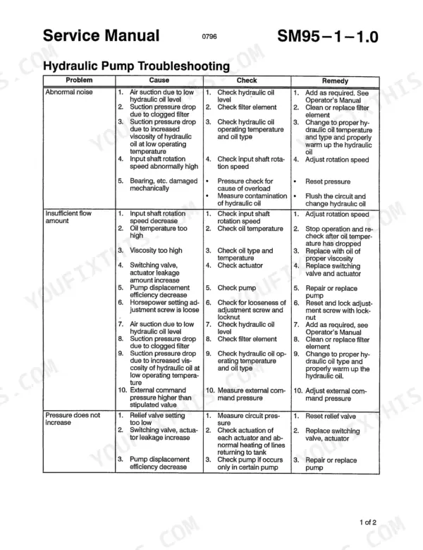
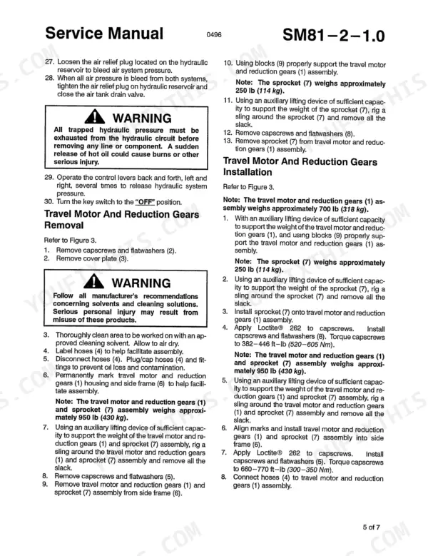
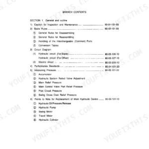
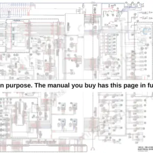
How a 4300's travel motor comes apart, and in what order it goes back together, is settled in one document: the 208-page Link-Belt 4300 service manual PDF, factory book No. 0896, covering the 4300 hydraulic excavator in both standard and Quantum series versions. Hydraulic system schematics sit beside electrical schematics for the heavy lift and power boost configurations, wiring diagrams and connector color codes included. Recondition procedures carry the main pump, pilot pump, travel and swing motors, main control valve, and the boom, arm, and bucket cylinders from disassembly through cleaning and inspection to final assembly. Torque the lower roller capscrews to 384-448 ft-lb (521-608 Nm) and the rotating joint lock bar capscrews to 181-214 ft-lb (245-290 Nm). Some days it's just you, the machine, and nobody left to ask. Bookmarked with a live text layer, this PDF puts swing motor troubleshooting two clicks from the cover; your answer is on screen before the wrench comes out.
What's Inside This Link-Belt 4300, 4300 Quantum Manual
| System | Pages | Key Topics |
|---|---|---|
| Lower Mechanism | 5-32 | Travel Motor and Reduction Gears, Take-Up Roller, Upper Rollers, Lower Rollers, Recoil Spring, Track Assembly |
| Upper Mechanism | 33-36 | Swing Motor and Reduction Gears |
| Engine | 37-40 | Throttle Motor |
| Hydraulic Equipment and Lines | 41-54 | Hydraulic System Schematic Diagram, Hydraulic Pump, Pilot Pump, Hydraulic System Cleaning Procedure, Rotating Joint |
| Controls | 55-64 | Joystick Control Valve, Travel/Service Control Valve, Main Control Valve |
| Attachment | 65-76 | Boom Cylinder, Arm Cylinder, Bucket Cylinder |
| Electric Parts | 77-86 | Electrical System Schematic Diagram with Heavy Lift, Electrical System Schematic Diagram with Power Boost, Monitor System Controller |
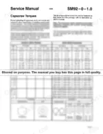
| Name Plates and Accessories | 87-94 | Capscrew Torques, Spare Pump |
| Spare Pump Recondition | 95-104 | Spare Pump Disassembly, Spare Pump Assembly, Shaft Seal Replacement, Troubleshooting Chart |
| Pilot Pump Recondition | 105-108 | Pilot Pump Disassembly, Pilot Pump Assembly, Shaft Seal Replacement |
| Hydraulic Pump Recondition | 109-136 | Hydraulic Pump Disassembly, Control Section Disassembly, Directional Control Valve Removal, Regulator Cover Disassembly, Rotary Group Removal, Central Gear Section Assembly |
| Travel Motor Recondition | 137-144 | Travel Motor Disassembly, Travel Motor Assembly, Travel Motor Reduction Gears Disassembly, Travel Motor Reduction Gears Assembly |
| Swing Motor Recondition | 145-152 | Swing Motor Disassembly, Swing Motor Assembly, Swing Motor Troubleshooting |
| Swing Reduction Gears Recondition | 153-158 | Swing Reduction Gears Disassembly, Swing Reduction Gears Assembly |
| Main Control Valve Recondition | 159-168 | Main Control Valve Disassembly, Main Control Valve Assembly, Cleaning and Inspection |
| Cylinder Recondition (Boom, Arm, Bucket) | 169-180 | Boom Cylinder Recondition, Arm Cylinder Recondition, Bucket Cylinder Recondition, Cylinder Disassembly, Cylinder Assembly |
| Joystick Control Valve, Recondition | 181-184 | Joystick Control Valve Assembly, Disassembly, Cleaning and Inspection, Assembly |
| Travel/Service Valve Control Valve, Recondition | 185-186 | Travel/Service Valve Control Valve, Disassembly, Cleaning and Inspection, Assembly |
| Rotating Joint, Recondition | 187-188 | Rotating Joint Assembly, Disassembly, Cleaning and Inspection, Assembly |
| Spool Solenoid Valve Assembly, Recondition | 189-190 | 8 Spool Solenoid Valve, Disassembly, Cleaning and Inspection, Assembly |
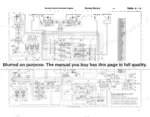
| Electrical System Schematics | 191-208 | Electrical System Schematic Diagram, Heavy Lift, Power Boost, Wiring Diagrams, Connector Color Codes |
Quick Reference Specifications
| Specification | Value | Page |
|---|---|---|
| Upper roller capscrews torque | 197-230 ft-lb (267-312 Nm) | p. 20 |
| Lower roller capscrews torque | 384-448 ft-lb (521-608 Nm) | p. 22 |
| Hydraulic pump mounting capscrews torque | 46-54 ft-lb (63-73 Nm) | p. 51 |
| Rotating joint lock bar capscrews torque | 181-214 ft-lb (245-290 Nm) | p. 50 |
| Pilot pump mounting capscrews torque | 21-26 ft-lb (28-35 Nm) | p. 46 |
| Grade 8 1/4 inch Dry Torque | 13-15 ft-lb | p. 89 |
| Metric Class 8.8 (Zinc Plated) M5 Dry Torque | 7-9 ft-lb | p. 90 |
| Capscrew (9) torque | 80 ft-lb (108 Nm) | p. 107 |
| Capscrews (2) torque | 73-87 ft-lb (98-118 Nm) | p. 140 |
| Capscrews (29,49) torque | 73-87 ft-lb (98-118 Nm) | p. 140 |
| Capscrews (53) torque | 394-532 ft-lb (534-721 Nm) | p. 148 |
| Capscrews (44) torque | 7-10 ft-lb (9-14 Nm) | p. 148 |
Link-Belt 4300, 4300 Quantum Common Problems This Manual Covers
Link-Belt 4300 swing brake will not release, machine has no swing in either direction
Verify pilot pressure at the swing brake release port before pulling the motor. If pressure checks good, remove the swing motor and follow the recondition steps starting on page 145. Pressure test the replacement oil seal to 7 PSI (5 kg/cm2), then torque the housing capscrews in a criss-cross pattern to 394-532 ft-lb (534-721 Nm).
Manual Section: Swing Motor Recondition p. 145No travel on either side after machine sits overnight or after repair work
Check the rotating joint first; an internal seal failure there kills travel to both sides at once. Remove and rebuild the joint using the procedure on page 187, replacing every seal in the kit. Apply Loctite 242 to the axle capscrews and torque them to 195-230 ft-lb (264-312 Nm) on reassembly.
Manual Section: Rotating Joint, Recondition p. 187Pilot pressure stays low, controls feel weak and functions respond slowly or not at all
Test pilot pressure at the pump outlet with the engine at operating speed before condemning anything downstream. Replace the pilot filter and retest. If pressure is still low, pull the pilot pump and recondition it per page 105, replacing the shaft seal. Torque the mounting capscrews to 21-26 ft-lb (28-35 Nm) on reinstall.
Manual Section: Pilot Pump Recondition p. 105Hydraulic pump makes abnormal noise and system pressure will not increase under load
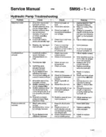
Check the suction side first; a starved pump gets noisy long before it fails. Verify tank oil level, inspect the suction line for collapse, and work through the troubleshooting chart on page 93 covering abnormal noise and pressure that does not increase. If the pump comes off for repair, torque the mounting capscrews to 46-54 ft-lb (63-73 Nm).
Manual Section: Hydraulic Pump Troubleshooting p. 93Track chain runs loose and lower rollers and idlers show rapid wear on rocky ground
Measure track tension and adjust at the recoil spring before throwing parts at it. Inspect lower rollers for flat spots and leaking seals, replace worn units, and torque their capscrews to 384-448 ft-lb (521-608 Nm) per page 22. Torque the take-up roller bearing cap capscrews to 200-230 ft-lb (271-312 Nm).
Manual Section: Lower Mechanism p. 5Frequently Asked Questions
How do I reset the monitor system controller on the Link-Belt 4300?
To reset the monitor system controller, press the 'Reset' switch for 20 seconds until a buzzer sounds or the clock displays all '9's. After turning the key switch OFF and back ON, you must set the language code, machine model number, and reset the computer gas emissions control as detailed on pages 84 and 85. p. 84
What are the torque specifications for Grade 8 alloy steel fasteners?
Torque specifications for Grade 8 alloy steel fasteners vary by diameter. For example, a 1/2 inch bolt requires 120-135 ft-lb (163-183 Nm) for dry torque, or 90-100 ft-lb (122-136 Nm) for lube torque. Refer to the table on page 89 for a complete list of sizes. p. 89
What is the procedure for bleeding air from the hydraulic pump?
To bleed the hydraulic pump, pressurize the hydraulic reservoir with 13 psi (0.9 kg/cm²) of compressed air. Loosen the air bleed plugs on top of the pump until air-free hydraulic oil flows out, then tighten the plugs and turn off the compressed air source. p. 47
What is the torque specification for the main control valve mounting capscrews?
The main control valve is secured to the upper frame using capscrews and spacers torqued to 125-132 ft-lb (170-180 Nm) in a criss-cross pattern. p. 167
What is the weight of the boom cylinder for the 4300 Quantum Series?
Each boom cylinder weighs approximately 615 lb (279 kg). p. 66
Is this Link-Belt 4300 manual a download or a disc?
You get a 208-page searchable PDF that downloads instantly after checkout. Open it on your laptop, tablet, or phone, and bring it right to the shop floor.
Is printing allowed for this Link-Belt 4300 Service Manual?
Yes. Print a single page or a chapter for your own shop use, on letter or A4.


Reviews
There are no reviews yet.