
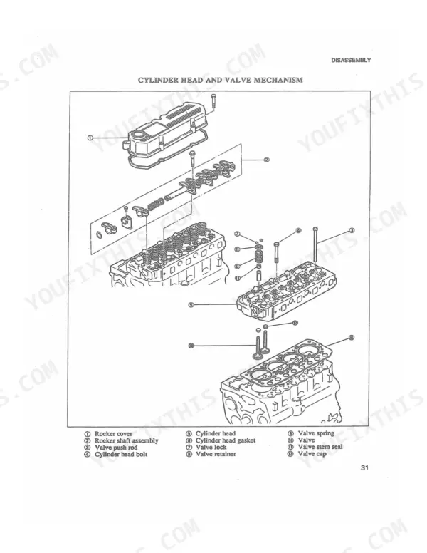
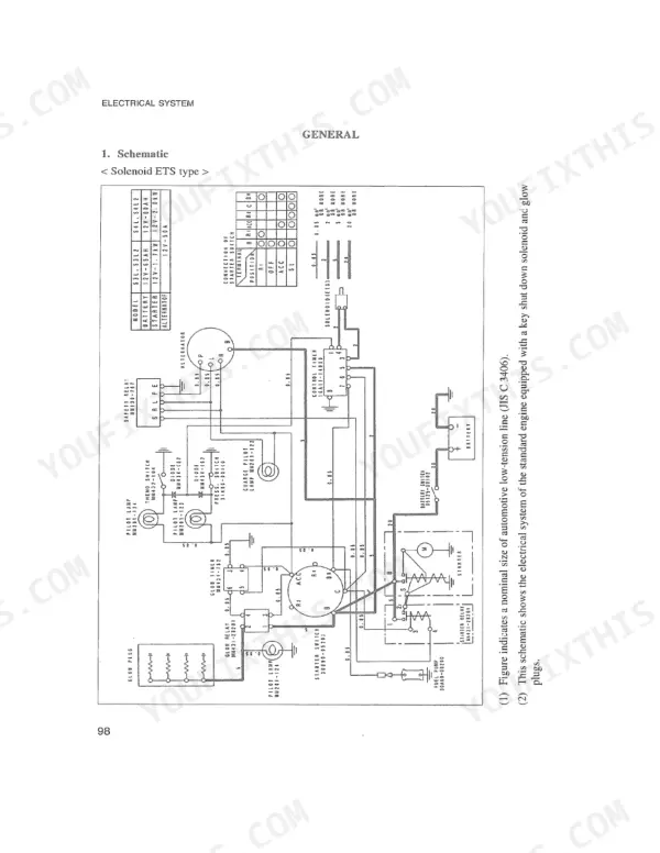
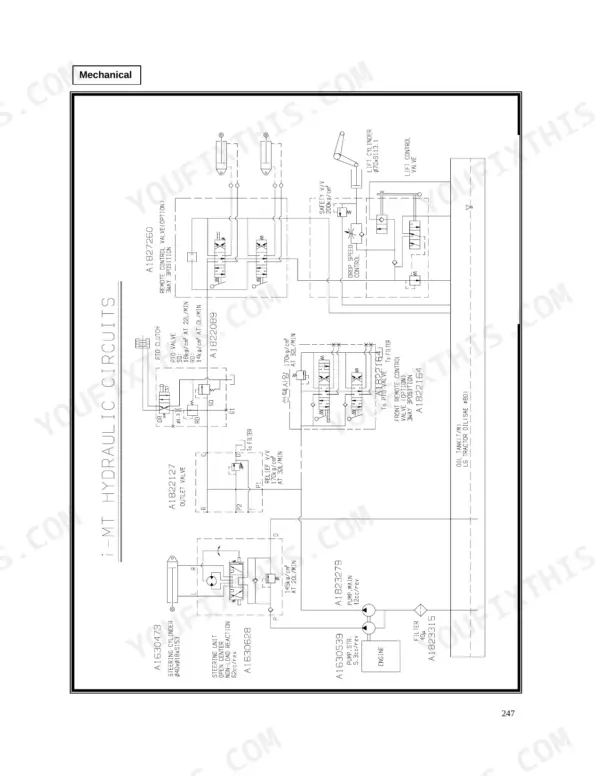
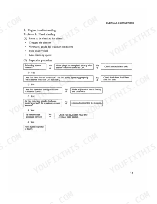

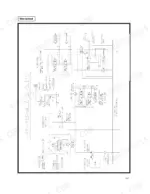
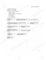
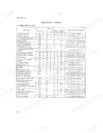
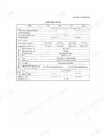
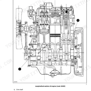
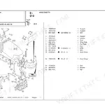
All 313 pages of this McCormick CT Series Service Manual zero in on two compact tractors: the CT28 and CT36, covering the S3L, S3L2, S4L, S4L2, I-HST, and I-MEC variants across both hydrostatic and mechanical transmission configurations. Inside, you get full wiring diagrams for both HST and mechanical tractor circuits, hydraulic schematics covering the complete lift, steering, and PTO valve circuits, page after page of exploded views across every major assembly, and a thorough troubleshooting section that walks through hard starting, fuel knock, low power, black exhaust smoke, and steering faults. Factory torque tables cover everything from cylinder head bolts to hydraulic housing fasteners; for example, torque the oil filter to 12 ± 1 N-m and set the down valve body spool clearance to 0.3–0.6 mm before sealing the control valve. No more chasing hydraulic gremlins through forum threads. Bookmarked and keyword-searchable: pull it up on your tablet at the machine and find the spec in seconds.
What's Inside This McCormick CT28, CT36 Manual
| System | Pages | Key Topics |
|---|---|---|
| Introduction | 1-3 | How to Use This Manual, Exploded Views, Symbols, Definition of Locational Terms, Service Data, Dimensional Tolerances |
| General Information | 4-9 | Model Identification and Serial Number Location, Component Location (S3L/S4L Engines), Specifications, Performance Curves, Prime Power Output |
| Engine Overhaul and Inspection | 10-69 | Determining When to Overhaul, Compression Pressure Measurement, Cylinder Head, Rocker Arms and Rocker Shaft, Valve Springs, Valves, Valve Guides and Seats, Pistons, Connecting Rods, Crankshaft, Timing Gears |
| Cooling System | 124-129 | Schematic, Specifications, Water Pump, Thermostat, Radiator, Inspection |
| Lubrication System | 130-133 | Schematic, Specifications, Oil Pump, Oil Pressure Switch, Relief Valve, Inspection |
| Fuel System | 134-151 | Fuel Injection Pump (Test on Engine, Disassembly, Inspection, Assembly), Governor, Fuel Pump, Fuel Filter, Injection Nozzle, Schematic, Specifications |
| Air Inlet and Exhaust System | 152-155 | Schematic, Air Cleaner, Intake and Exhaust Manifold, Inspection |
| Engine Maintenance and Adjustments | 156-169 | Lubrication and Maintenance Chart, Engine Oil and Oil Filter, Valve Clearance, Fuel Injection Timing, Fuel System Priming, Idle RPM Setting, Injection Nozzle, Fan Belt |
| Engine Specifications, Tightening Torques and Special Tools | 170-178 | Engine Specifications, Tightening Torques, Sealants, Special Tools, Basic Engine Components, Lubrication / Fuel / Air Inlet Systems |
| Transmission | 179-232 | Main Gear (Center Case), Range Gear (Axle Case), Final Drive Shaft, Differential and Rear Axle, Schematic View, Running Speed, Clutch Disassembly and Assembly, HST Unit Disassembly and Assembly, HST Operation |
| Front Axle | 233-248 | Main Bolt Tightening Force, Knuckle Configuration, King Pin, Taper Bearing, Front Wheel Pinion and Differential, Pinion Center Distance Adjustment, Differential Assembly |
| Hydraulic System (3-Point Lift and PTO) | 249-287 | Main Specification, Hydraulic Pump, Independent PTO, Front Outlet Valve, Control Valve, Lifting / Neutral / Down Positions, Hydraulic Circuit (Mechanical and HST), Link Assembly and Disassembly |
| Steering System | 249-287 | Steering Unit, Steering Pump, Steering Cylinder, Relief Valve, Spool and Rotor, Rotor Shaft Disassembly and Assembly, Steering Troubleshooting |
| Electrical System | 288-313 | Starter Motor (Magnetic Switch, Brush Holder, Yoke, Armature, Pinion Shaft), Alternator (Rectifier Bridge, Stator, Slip Ring, Voltage Check), Glow Plug System, Key Shutoff Solenoid, Circuit Diagrams (HST and Mechanical Tractor) |
Quick Reference Specifications
| Specification | Value | Page |
|---|---|---|
| Knuckle arm liner (adjustment types) | 0.1mm, 0.5mm | p. 234 |
| Clearance between body and plate of spool (gap between down valve and plate) | 0.3~0.6mm | p. 267 |
| Upper link length | 480 ~ 700 mm | p. 264 |
| Lift rod length | 430 ~ 540 mm | p. 264 |
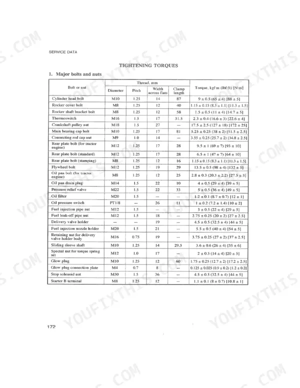
| Oil filter torque | 1.2 ±0.1 kgf-m (8.7 ± 0.7 lbf-ft) [12 ± 1 N-m] | p. 175 |
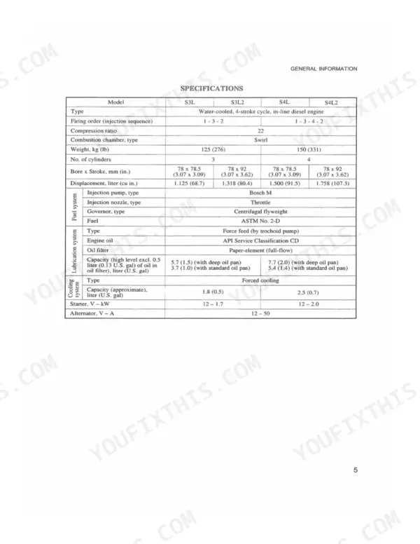
| Compression Ratio | 22 | p. 8 |
| Valve Clearance (Inlet and Exhaust) | 0.25 mm | p. 157 |
| Fuel Injection Pressure (Standard) | 140 kgf/cm² | p. 135 |
| Crankshaft Pulley Nut Torque | 17.5 ± 2.5 kgf-m | p. 175 |
| Main Bearing Cap Bolt Torque | 5.25 ± 0.25 kgf-m | p. 175 |
| Fan Belt Deflection (under 10 kgf [98 N] force) | 10 to 12 mm | p. 169 |
| Thermostat Opening Temperature | 82 ± 1.5°C | p. 125 |
McCormick CT28, CT36 Common Problems This Manual Covers
Engine overheats during field work, coolant temperature gauge climbs into the red
Test the thermostat in hot water: it must begin opening at 82 plus or minus 1.5 degrees C (page 125). Replace it if stuck closed. Inspect the water pump impeller for erosion and check fan belt deflection; correct deflection is 10 to 12 mm under 10 kgf (98 N) of force (page 169).
Manual Section: Cooling System p. 125Diesel knock and black exhaust smoke at full throttle, noticeable power loss
Remove and bench-test each injection nozzle; standard opening pressure is 140 kgf/cm2 (page 135). A nozzle worn below this threshold dribbles fuel instead of atomizing it, producing black smoke. Clean or replace nozzle tips as described in the Fuel System section starting on page 134, then retest injection timing after reinstallation.
Manual Section: Fuel System p. 135Engine idles rough or hunts at low RPM, stalls when returning to idle
Adjust valve clearance with the engine fully cold; both inlet and exhaust valves are set to 0.25 mm (page 157). Also verify idle RPM is within spec. The Maintenance section on page 156 covers valve clearance, injection timing, and idle adjustment in one sequence. Do not set clearance on a warm engine.
Manual Section: Maintenance p. 157Frequently Asked Questions
What are the torque specs for engine bolts on CT Series?
For the cylinder head bolt, the tightening torque is 9 ± 0.5 kgf-m (65 ± 4 lbf-ft) [88 ± 5 N-m]. The main bearing cap bolt requires a torque of 5.25 ± 0.25 kgf-m (38 ± 2 lbf-ft) [51.5 ± 2.5 N-m]. The connecting rod cap nut should be tightened to 3.55 ± 0.25 kgf-m (25.7 ± 2 lbf-ft) [34.8 ± 2.5 N-m]. p. 175
How do you fix CT Series steering bracket cracks under front loader load, steering becomes loose?
Inspect the front axle knuckle arm liner clearance on both sides before reinstalling the loader. The Knuckle Configuration section on page 234 lists shim sizes of 0.1 mm and 0.5 mm to restore proper fit. Replace any cracked cast bracket before resuming loader work; avoid combining full steering lock with full loader curl. p. 234
How do you fix hydraulic three-point hitch won't raise or lowers on its own, implement dragging?
Remove the control valve and measure the gap between the spool body and down valve plate; the specification on page 267 is 0.3 to 0.6 mm. Clean the valve body and replace O-rings if the spool sticks. Also verify upper link length is set between 480 and 700 mm before reassembling the three-point linkage. p. 267
How do you fix engine cranks slowly or won't fire in cold weather, glow plugs not heating?
Test each glow plug individually with a multimeter and verify the automatic glow timer activates for 6.2 plus or minus 0.7 seconds (page 121). An open-circuit plug or failed timer relay will leave cylinders cold on startup. Check the wiring diagram on page 101 to trace the timer circuit; replace any plug that fails the resistance test. p. 121
How quickly can I access this CT Series & variants manual after buying?
Immediate download of the complete 313-page searchable Service Manual. Access it on any device, from a laptop at your desk to a phone in the field.
Are
Yes. Print a chapter or just the pages for the job at hand, for use in your own shop. Any home or office printer works.
Reviews
There are no reviews yet.