
Part of the Case Repair Manuals.
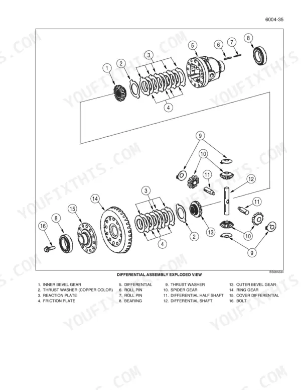
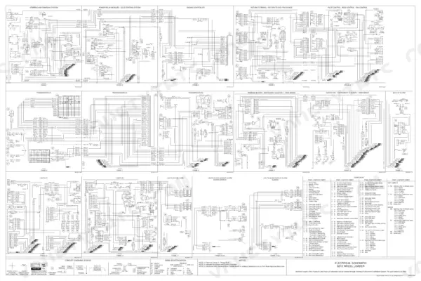
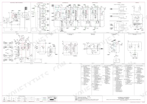
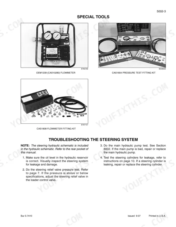
This 936-page Case 621E Wheel Loader Service Manual (OEM #84243974) breaks down the 621E Tier 3 from engine and steering to power train, brakes, and hydraulics. Inside you get full electrical and hydraulic schematic foldouts, wiring pinouts for the instrument cluster and relay modules, and a dedicated troubleshooting section covering steering, transmission, and hydraulic pressure checks. You also get exploded views for teardown work, plus page after page of torque tables and clearance specs. Torque the engine drive shaft to coupler bolts to 53-62 Nm, and fill the cooling system to 36.0 liters. Stop tracing wires off a bad photocopy. This bookmarked PDF opens on your phone or tablet, so you can jump straight to the hydraulics section and get your loader back to work.
What's Inside This Case 621E, 621E Tier 3 Manual
| System | Pages | Key Topics |
|---|---|---|
| General | 7-26 | Section Index - General, Standard Torque Specifications, Fluids and Lubricants, Metric Conversion Chart |
| Engines | 27-66 | Section Index - Engines, Engine and Radiator Removal and Installation, Stall Tests, After Cooler, For Engine Repair, See Engine Service Manual |
| Fuel System | 67-68 | Section Index - Fuel System, For Fuel System Repair, See the Engine Service Manual |
| Electrical | 69-302 | Section Index - Electrical, Removal and Installation of Starter and Alternator, Electrical Specifications and Troubleshooting, Batteries, Instrument Cluster |
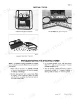
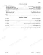
| Steering | 303-402 | Section Index - Steering, Removal and Installation of Steering Components, Steering Specifications, Pressure Checks, And Troubleshooting, Steering Cylinders, Center Pivot |
| Power Train | 403-650 | Section Index - Power Train, Removal and Installation of Power Train Components, Transmission Specifications, Pressure Checks, And Troubleshooting, Transmission, Front Axle |
| Brakes | 651-690 | Section Index - Brakes, Removal and Installation of Brake Components, Hydraulic Brake Troubleshooting, Brake Pump, Brake Accumulators, Parking Brake |
| Hydraulics | 691-838 | Section Index - Hydraulics, How to Read Hydraulic Schematics, Removal and Installation of Hydraulic Components, Hydraulic Specifications, Troubleshooting, And Pressure Checks |
| Mounted Equipment | 839-932 | Section Index - Mounted Equipment, Air Conditioning Troubleshooting and System Checks for Systems with HFC-134a Refrigerant, Air Conditioner System Service |
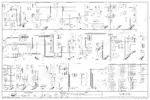
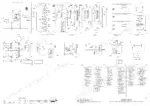
| Electrical and Hydraulic Schematics | 933-936 | Full-Size Electrical Wiring Schematics, Hydraulic System Schematics, Foldout Circuit Diagrams, Component and Connector Reference |
Quick Reference Specifications
| Specification | Value | Page |
|---|---|---|
| Engine Drive Shaft to Coupler Bolts Torque | 53 to 62 Nm (39 to 46 pound feet) | p. 631 |
| Power Relay Module A, Ignition Power (fuse A) | 105 A | p. 933 |
| Power Relay Module B, Ignition Power (fuse A) | 105 A | p. 933 |
| Engine Oil Capacity | 13.2 liters (14 U.S. Quarts) | p. 17 |
| Engine Cooling System Capacity | 36.0 liters (38 U.S. Quarts) | p. 17 |
| Fuel Tank Capacity | 246 liters (65 U.S. Gallons) | p. 17 |
| Hydraulic System Total System Capacity | 147.6 liters (39 U.S. Gallons) | p. 17 |
| Transmission Refill Capacity with Filter Change | 19.9 liters (21 U.S. Quarts) | p. 17 |
| Transmission Total System Capacity | 26.7 liters (28.2 U.S. Quarts) | p. 17 |
| Front Axle Capacity | 22.0 liters (23.2 U.S. Quarts) | p. 17 |
| Rear Axle Capacity | 22.0 liters (23.2 U.S. Quarts) | p. 17 |
| Steering Cylinder Torque for Piston Cap Screw | 810 to 925 Nm (597.5 to 682 pound feet) | p. 331 |
Case 621E, 621E Tier 3 Common Problems This Manual Covers
Instrument cluster displays a steering fault code operator cannot identify or clear
Pull the exact fault code from the instrument cluster; cross-reference it against the steering error list to isolate a sensor, valve, or wiring problem. Check the steering cylinder piston cap screw torque of 810 to 925 Nm (597.5 to 682 pound feet) from page 331; a loose cylinder can trip the position sensor. Clear the code and retest.
Manual Section: SteeringDash shows an electronic control module fault and engine won't crank in cold weather
Check power relay module A and B ignition power circuits first; both are rated at 105 A per the schematic on page 933, and a tripped or corroded relay reads as loss of ECM communication. Pull the relays, inspect the pins for corrosion, and test continuity across each socket. Reseat firmly and clear the fault code before attempting a cold start.
Manual Section: Electrical and Hydraulic Schematics p. 933Frequently Asked Questions
What are the torque specifications for Case 621E wheel lug bolts?
The wheel lug bolts for the Case 621E should be initially tightened to 298 Nm (220 pound-feet) in the sequence shown in Figure 1. A final torque of 640 to 720 Nm (475 to 530 pound-feet) should then be applied in the same sequence. p. 641
How do you fix case 621E wheel loader loses all hydraulic and drive functions suddenly while working?
Remove the drive shaft cover and inspect the fiber coupling between engine and transmission for cracking or complete disintegration. Torque the coupler to flywheel bolts and drive shaft to coupler bolts to 53 to 62 Nm (39 to 46 pound feet) per page 631. Replace the coupling immediately if worn; a broken coupling shreds the transmission input gear. p. 631
How do you fix loud rattling noise from the engine compartment during startup when cranking the starter motor?
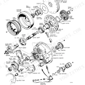
Check the fiber coupling between the engine and transmission first; a failing coupling rattles before it fails completely and takes out the transmission. Reference the exploded parts view to identify the coupler assembly, then torque the coupler to flywheel bolts to 53 to 62 Nm (39 to 46 pound feet). Replace any coupling showing surface cracks.
How do you fix transmission input gear teeth found completely rounded off and stripped during teardown inspection?
Pull the transmission input shaft and inspect every tooth for rounding or complete stripping; this damage almost always follows an unnoticed coupling failure. Start troubleshooting in the Power Train section beginning on page 403 and check coupler bolt torque at 53 to 62 Nm (39 to 46 pound feet) before reinstalling. Replace the input gear if teeth are worn. p. 403
Is this Case 621E manual a download or a disc?
A 936-page SERVICE MANUAL in searchable PDF format, available the moment you complete checkout. View on computer, tablet, or phone, with no shipping wait.
Can I print just the pages I need from this Case 621E manual?
Yes. Many mechanics print the section they need for their own shop and bring it to the bench.
Does this Case 621E manual show the hydraulic circuits?
Included. Hydraulic system schematics cover all circuits, control valves, and component specifications for the Case 621E, Wheel Loader, 621E Tier 3.









Reviews
There are no reviews yet.