


Part of the John Deere Repair Manuals.
Need factory rebuild data for your John Deere 6076 engine? This 437-page Technical Manual (OEM #CTM6) covers the 6076 powerplant across the 644E, 644EH, 644ER, 740E, and 740EH lineup. Inside: a complete disassembly-to-assembly rebuild sequence, inch and metric torque charts, and step-by-step diagnostics for every major system, from cylinder head and crankshaft to turbocharger, fuel injection, and cooling. The operation and test section walks you through dynamometer testing, compression pressure checks, and injection pump timing with factory thresholds. Torque A-Series injection pump drive gear cap screws to 47 N·m (35 lb-ft), or 61 N·m (45 lb-ft) for P-Series. No more chasing specs through forum threads. Bookmarked and keyword-searchable: pull it up on any device and jump straight to the system you're working on.
What's Inside This John Deere 6076 Engines Manual
| System | Pages | Key Topics |
|---|---|---|
| Safety & Precautions | - | Introduction and Safety Information, Handle Fluids Safely, Prevent Battery Explosions, Avoid High-Pressure Fluids, Wear Protective Clothing, Use Proper Lifting Equipment, Use Proper Tools |
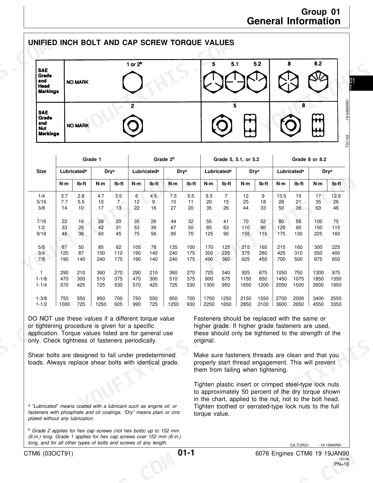
| General Information & Fluids | - | Inch Series Torque Chart, Metric Series Torque Chart, Bolt Identification Chart, Engine Model Designation, Basic 6076 Engine Specifications, Engine-Sectional View, Diesel Fuel, Diesel Engine Oil, General Purpose Grease, Engine Coolant Recommendations & Requirements |
| Engine Mounting & Rebuild Procedures | - | Engine Repair Stand, Install 400 Series Adapters, Engine Lifting Procedure, Mount Engine on Repair Stand, Clean Engine, 6076 Engine Disassembly Sequence, Sealant Application Guidelines, 6076 Engine Assembly Sequence |
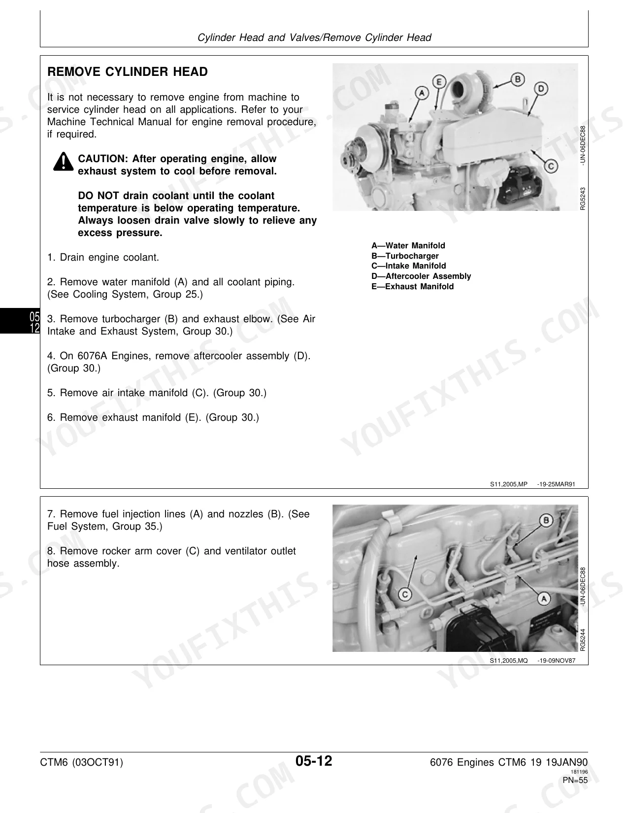
| Cylinder Head, Block, Pistons & Rods | - | Cyl. Head and Valve Specifications, Check and Adjust Valve Clearance, Remove/Install Cylinder Head, Torque-Turn Flanged-Head Cap Screws, Remove Pistons and Connecting Rods, Inspect Pistons and Liners, Install Cylinder Liners and Pistons |
| Crankshaft, Camshaft & Timing Gear Train | - | Remove Crankshaft Main Bearings, Inspect Crankshaft, Replace Flywheel Ring Gear, Install Main Bearings and Crankshaft, Check Valve Lift, Remove Camshaft, Measure Camshaft Lobe Lift, Assemble Camshaft, Install Timing Gear Cover and Auxiliary Drive Gear |
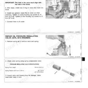
| Lubrication & Cooling Systems | - | Engine Crankcase Oil Fill Quantities, Inspect Oil Pressure Regulating Valve, Install Engine Oil Pump, Remove Water Pump, Disassemble Water Pump, Inspect and Tension Fan and Alternator V-Belts |
| Air Intake, Exhaust & Fuel System | - | Remove/Install Turbocharger, Remove/Inspect/Install Exhaust Manifold Assembly, Fuel Filters, Fuel Check Valve Assembly, Fuel Supply Pump, Aneroid, Fuel Shutoff Solenoid, Fuel Injection Nozzles |
| Tune-Up | - | Preliminary Engine Testing, Crankcase Ventilation System, Air Intake System, Exhaust System, Cooling System, V-Belts, Electrical System |
| Engine, Air Intake & Fuel System Operation and Test | - | Dynamometer Test, Engine Compression Pressure, Valve Clearance & Lift, Vibration Damper, Crankshaft End Play, Engine Oil Pressure, Turbocharger & Aftercooler, Intake Manifold Pressure, Air Filter Restriction Indicator Switch Test, Fuel System Operation, Injection Pump Timing Check |
| Dealer Fabricated Tools | - | - |
| Alphabetical Component Index | - | Air Cleaner, Bearings & Bushings, Break-In Engine Procedure, Crankshaft, Cylinder Head, Cylinder Liners, Electrical System, Flywheel, Fuel Injection Pump & Nozzles, Oil Pump & Oil Pan, Radiator & Thermostat, Valve Guides & Seats |
Quick Reference Specifications
| Specification | Value | Page |
|---|---|---|
| Crankshaft Rear Oil Seal to-Housing Maximum Runout | 0.152 mm (0.0060 in.) | p. 131 |
| Rear Crankshaft Oil Seal Housing torque | 27 N·m (20 lb-ft) | p. 132 |
| Fuel supply pump replacement | Replace pump if spindle seal is defective or spindle is worn | p. 318 |
| Injection Pump Drive Gear-to-Pump Hub Cap Screws (A-Series Injection Pumps) | 47 N·m (35 lb-ft) | p. 306 |
| Injection Pump Drive Gear-to-Pump Hub Cap Screws (P-Series Injection Pumps) | 61 N·m (45 lb-ft) | p. 306 |
| Valve rotators replacement | Replace if defective | p. 59 |
| Rocker Arm Cover-to-Cylinder Head torque | 8 N·m (6 lb-ft) (72 lb-in.) | p. 48 |
| Rocker Arm Shaft O.D. | 19.01—19.05 mm (0.7484—0.7500 in.) | p. 56 |
| Rocker Arm I.D. | 19.07—19.10 mm (0.7507—0.7520 in.) | p. 56 |
| Engine Oil Pressure @ 1900 RPM (Max) | 380 kPa (55 psi) | p. 209 |
| Oil Filter Bypass Valve Operating Pressure | 210 kPa (30 psi) | p. 209 |
| Cylinder Head-to-Cylinder Block Torque (SAE Grade 180 or 12.9, Step 2) | 245 N·m (180 lb-ft) | p. 48 |
John Deere 6076 Engines Common Problems This Manual Covers
John Deere 6076 rear crankshaft oil seal migrated in housing, engine oil shows transmission hydraulic contamination
Check the transmission vent cap for plugging first. Inspect seal housing runout; maximum allowable is 0.152 mm (0.0060 in.) per page 131. Remove the seal and wear sleeve as a unit and replace with a new complete assembly per page 166. Torque housing cap screws to 27 N·m (20 lb-ft) per page 132.
Manual Section: Crankshaft, Main Bearings and Flywheel p. 131Fuel contaminating engine oil, transfer pump spindle seal failed, oil level rising between changes
Remove the fuel supply pump and inspect the spindle for wear and the seal for defects. Replace the pump if the spindle is worn or the seal is defective per page 316. After installing a new pump, drain the contaminated crankcase oil completely and refill to capacity: 25.0 L (26.5 qt) per page 210.
Manual Section: Fuel System p. 316Engine hard to start hot or cold, smoke on cranking with fuel smell, injection pump timing retarded
Verify injection pump timing first; retarded timing is the root cause of hot no-start with smoke on this engine. Adjust per Fuel System Operation and Tests procedures. If the pump is defective, remove and repair per page 407. Torque A-Series drive gear cap screws to 47 N·m (35 lb-ft) or P-Series to 61 N·m (45 lb-ft) per page 334.
Manual Section: Fuel System Operation and Tests p. 407Engine overheats under load at normal operating hours, coolant level full, water pump and thermostat suspected
Inspect the thermostat by testing in hot water before swapping major components. Check coolant level and look for blockages in passages, hoses, and the radiator under the Cooling System Malfunctions procedures. If the water pump was recently serviced, verify mounting cap screws are torqued to 47 N·m (35 lb-ft).
p. 242Frequently Asked Questions
What are the recommended service intervals?
The manual recommends replacing the vibration damper every 5 years or 4500 hours, whichever occurs first. Additionally, when using John Deere TORQ-GARD SUPREME PLUS-50™ engine oil and a John Deere oil filter, the oil change interval may be extended by 50 hours. p. 137
What fluids and capacities does this machine require?
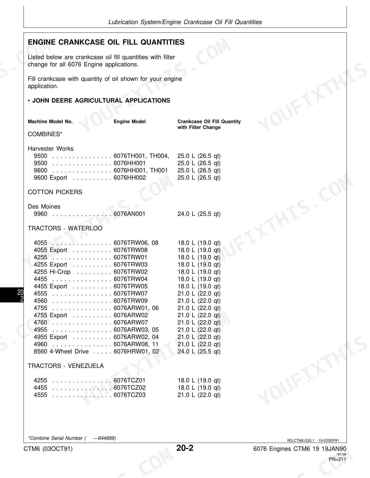
The machine requires Grade No. 1-D or Grade No. 2-D diesel fuel (or ISO 1585 commercial diesel fuel in European countries). Engine oil should meet API Service Classification CE or CD, Military Specification MIL-L-2104E/D/C, or CCMC Specification D4 or D5. For example, a 9500 Combine requires 25.0 L (26.5 qt) of crankcase oil with a filter change. Grease should be John Deere Moly High Temperature EP Grease or SAE Multipurpose EP Grease. Coolant should be ethylene-glycol type, meeting GM1899M or GM6038M, or John Deere Engine Cooling Fluid/Low Silicate Antifreeze. p. 210
How to troubleshoot engine won't start?
If the engine will not start, potential problems include an empty fuel tank, a fuel shut-off cable not pushed in, improper fuel, a plugged fuel filter, or fuel shut off at the tank. Electrical system malfunctions such as corroded or loose battery connections or a weak battery can also prevent the engine from starting. p. 368
What torque specifications are listed?
The manual lists various torque specifications for engine components. For example, Unified Inch Bolts and Cap Screws (Grade 8 or 8.2, lubricated) have a torque of 13.5 N·m (10 lb-ft) for 1/4 inch size. Cylinder Head-to-Cylinder Block cap screws (SAE Grade 180 or 12.9 with washers) are tightened to 224 N·m (165 lb-ft) in Step 1. Connecting Rod Caps (Initial, Blind Hole Cap Screws) require 27 N·m (20 lb-ft). p. 15
What are the common electrical problems?
Common electrical problems that can prevent the engine from starting include corroded or loose battery connections and a weak battery. Additionally, if batteries are undercharged or overcharged, it may indicate issues with the alternator or charging circuit, which should be checked. p. 368
How quickly can I access this manual after buying?
You get a 437-page searchable PDF that downloads instantly after checkout. Open it on your laptop, tablet, or phone, and bring it right to the shop floor.
Can I print specific sections of this John Deere 6076 Engines Technical Manual?
Absolutely. No DRM or copy protection. Print the whole manual or just the pages you need. Any home or office printer works.


Reviews
There are no reviews yet.