

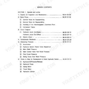
Link-Belt's LS-2800CII hydraulic excavator is the one machine covered by OEM document WEL2802-1E, a 410-page Link-Belt LS-2800CII shop manual PDF; if that model sits in your shop, this is its book. Hydraulic schematics trace oil from the main pump through the control valve out to the swing motor, travel motors, and boom, arm, and bucket cylinders, while wiring diagrams map the monitor display, controller, and throttle motor circuits. Travel motor and reduction gear work alone fills roughly a third of the volume, backed by full disassembly and reassembly sequences for the pump, pilot valve, rotating joint, and cylinders. Pressure-test cylinder oil seals against the 2 kgf/cm² (28.4 psi) standard, then pull the P1 and P2 pump ports to 9.0 to 11.0 kgf-m. Guess at those numbers and you fund the second teardown yourself. Bookmarked and text-searchable, the file travels wherever the machine does.
What's Inside This Link-Belt LS-2800CII Manual
| System | Pages | Key Topics |
|---|---|---|
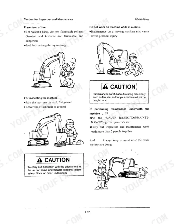
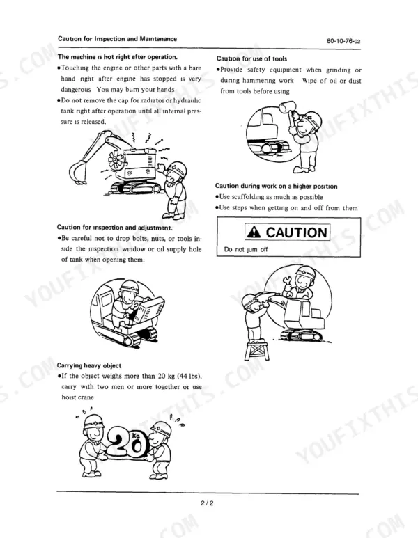
| Caution for Inspection and Maintenance, Basic Rules | 5-12 | Prevention of Fire, General Rules for Disassembling, General Rules for Reassembling |
| Hydraulic and Electric Circuits, Performance Standards | 13-24 | Main Pump, Swing Motor, Traction Motor, Control Valve, Monitor Display, Controller, Adjustment and Performance Test |
| Traction Motor, Reduction Gear and Drive Assembly | 25-152 | Travel Motor, Traction Drive Installation, Bolt Tightening Torque, Oil Stopper for Suction Strainer |
| Take-Up Roller and Track Roller | 153-190 | Structural Diagrams, Tools and Jigs, Disassembly and Reassembly Procedures, Maintenance Standards |
| Grease Cylinder, Recoil Spring and Roller | 191-206 | Structural Diagram, Disassembly Procedure, Reassembly Procedure, Maintenance Standards |
| Shoe and Drive Sprocket | 207-212 | Structural Diagram, Disassembly and Reassembly, Maintenance Standards |
| Swing Motor and Reduction Gear | 213-248 | Specifications, Function and Structure, Causes of Trouble and Remedies, Motor Structure, Disassembly |
| Engine Mounting | 249-250 | Bolt, Cushion Rubber |
| Hydraulic Pump and Pump Installation | 251-310 | Specifications, Details of Parts, Tools and Jigs, Disassembly, Coupling, Pump Input Shaft, Engine Flywheel |
| Rotating Joint | 311-316 | Structural Diagram, Tools and Reassembly Procedure |
| Pilot Valve | 317-340 | Summary and Specifications, Construction and Functions, Maintenance |
| Control Valve | 341-364 | Outline, Disposition, Notes for Handling, Disassembling and Reassembling |
| Hydraulic Cylinder | 365-384 | Disassembly and Assembly Procedures, Trouble, Maintenance Standards |
| Service Monitoring System | 385-400 | Outline and Performance, Disassembly and Reassembly |
| Weights, Maintenance Standards and Conversion Tables | 401-410 | Lower Mechanism, Upper Machinery, Counter Weight, Turntable Bearing, Back-Hoe Attachment Standards, Conversion Table |
Quick Reference Specifications
| Specification | Value | Page |
|---|---|---|
| Travel bend (2) - difference in time required for 5 idle turns of the sprocket | 5% | p. 19 |
| Air bleeding plug tightening torque | 0.7 to 0.9 kgf-m | p. 34 |
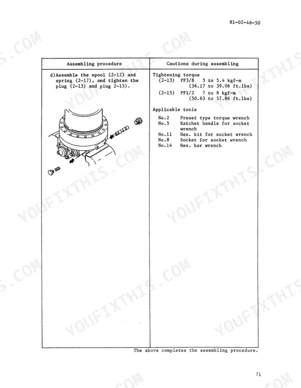
| P1 and P2 ports tightening torque | 9.0 to 11.0 kgf-m | p. 34 |
| Pressure resistance of oil seal (Ordinary) | 2 kgf/cm² (28.4 psi) | p. 65 |
| Pressure resistance of oil seal (Maximum) | 5 kgf/cm² (71.1 psi) | p. 65 |
| Air pressure for track roller assembly leak check | 2 kgf/cm² (14 ft.lb) | p. 187 |
| Oil fill amount for LS-2650CII track roller | 160 cc (5.28 oz) | p. 187 |
| LS-2800CII Spring Mounting Length | 557 mm (21.93 inches) | p. 203 |
| Bending radius for buffer ring | 6mm (0.24 in) | p. 376 |
| Travel Motor Lubricant Initial Replacement Interval | 100 to 250 hours | p. 31 |
| Travel Motor Lubricant Second and Subsequent Replacement Interval | 1000 to 1500 hours | p. 31 |
| Swing Motor Lubricant Replacement Interval | 1000 to 1500 hours | p. 115 |
Link-Belt LS-2800CII Common Problems This Manual Covers
Link-Belt LS-2800CII travel motor won't run or one track crawls slow, machine pulls to one side
Check the troubleshooting steps starting before pulling the motor. Verify parking brake release pressure and inspect the counterbalance valve for sticking. If the case weeps, test the oil seal; it should hold 2 kgf/cm² (28.4 psi). Drain and refill reduction gear lubricant at the 1000 to 1500 hour interval listed on page 31.
Manual Section: Traction Motor and Reduction GearMain pump whining under load, boom and arm slow, pressure won't build
Test pump flow and pressure before condemning downstream valves. Inspect the suction strainer using the oil stopper procedure on page 23 so you don't have to drain the tank. If the pump comes out, rig a hoist first; the assembly weighs 130 kg. Bleed air at the pump port after reinstall, following the notes on page 21.
Manual Section: Hydraulic Pump p. 251Track thrown twice this month, tension goes slack a few hours after adjusting
Grease the track adjuster and watch whether the grease cylinder bleeds back; a leaking check valve won't hold tension. Measure the recoil spring installed length against the 557 mm (21.93 in) spec on page 203, following the disassembly procedure that starts on page 198. Inspect roller and idler flanges for wear while the track is off.
Manual Section: Recoil Spring and Roller p. 198Joystick response sluggish, functions creep in neutral or need extra lever throw
Measure pilot circuit pressure first; primary supply should be 100 kgf/cm² as listed on page 317. Low or unstable secondary pressure points to worn spools or weak return springs inside the pilot valve. Disassemble per the maintenance procedure, clean every part in clean hydraulic oil, and replace any O-rings you disturb.
Manual Section: Pilot Valve p. 317Boom drifts down overnight, fresh oil film on the cylinder rod every shift
Wipe the rod and cycle the boom to tell whether oil is passing the rod seal or the piston is bypassing internally. Replace the full seal kit, not single seals, and keep the buffer ring bending radius at least 6 mm (0.24 in) during installation, per page 376. Inspect the rod for pitting and check pin bushings before reassembly.
Manual Section: Hydraulic Cylinder p. 365Frequently Asked Questions
What are the replacement specifications for oil seals?
When assembling an oil seal, apply grease to prevent early dry friction. For a single lip type, apply grease uniformly to the entire periphery on the opposite side of the lip's seal end. For a double lip type, apply grease to 40-60% of the lip's space. Ensure the contact surface (shaft area) is free of dust, flaws, or rust, and apply grease or lubrication oil for smooth installation. p. 11
What are the replacement specifications for O-rings?
O-rings should be coated with oil before installation to avoid flaws, especially since silicon rubber is easily torn. If an O-ring has been hardened after long storage, it must be discarded even if unused. Only use O-rings specified in the detailed parts list, as special materials like silicon rubber are used for heat resistance in engine areas. p. 11
What is the required oil capacity for the travel motor casing?
When replacing the travel motor or performing maintenance, the oil capacity required in the casing is 60 liters (1.58 gallons). p. 22
What is the tightening torque for the main body mounting bolts on the travel motor?
The main body mounting bolts (30-M16) for the travel motor require a tightening torque of 27.2 to 31.8 kgf-m (197 to 230 ft-lb). p. 22
What is the lubricant replacement interval for the speed reducer's case?
The lubricant replacement interval for the speed reducer's case, based on the engine hour meter, is 100 to 250 hours for the initial replacement, and every 1000 to 1500 hours for second and subsequent replacements. p. 31
Is this Link-Belt LS-2800CII manual a PDF I download?
Instant PDF download. You get the full 410-page searchable Shop Manual immediately after payment. Open it on your laptop, tablet, or phone right in the shop.
Am I able to print pages from this Link-Belt LS-2800CII manual?
Yes. Many mechanics print the section they need for their own shop and bring it to the bench.



Reviews
There are no reviews yet.