

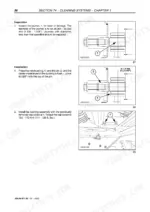
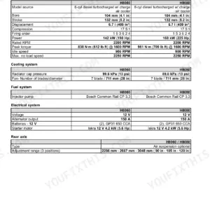
Part of the New Holland Repair Manuals.
3,516 pages of factory repair procedures for the New Holland CR920, CR940, CR960, CR970 and CR980 combines (print number 604.64.971.00, dated 05-2003 in the page footers).
Seventeen sections cover the machine bolt by bolt: 7.5L engine remove and replace with 7.8L and 10.3L operation coverage, engine gearbox and clutch pack rebuild, transmission, planetary final drives, and the hydrostatic drive with the fill and start-up procedure. The 114 l/min hydraulic system with stack valve overhaul follows, then steering axle, climate control, feeder house, rotors, cleaning shoe, grain handling and straw chopper.
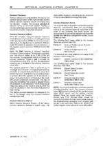
The electrical coverage runs from InfoView diagnostics through full schematics and the CAN bus to six dedicated fault code chapters. Native two-level PDF bookmarks throughout.
What's Inside This New Holland CR920-CR980 Repair Manual
| System | Pages | Key Topics |
|---|---|---|
| General Information and Machine Index | 1-60 | 7.5L New Holland Engine, Cooling System, Remove and Replace, 7.5L NH Engine, Fuel System, 7.8L, 10.3L Description of Operation, Engine, Engine Gearbox, Clutch Pack Removal/Installation |
| Engine (Section 10) | 61-438 | 7.5L Engine, Cooling System, Remove and Replace, 7.5L NH Engine, Fuel System, 7.8L, 10.3L Description of Operation, Engine, Engine Module Common Components |
| Live PTO (Section 14) | 439-522 | Engine Gearbox, Clutch Pack Removal/Installation, Clutch Pack Rebuild, Engine Gearbox Removal/Installation, Engine Gearbox Rebuild |
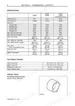
| Transmission (Section 21) | 523-576 | Specifications, Tightening Torques, Special Tools, Gearbox Shafts, Shifting Diagram, Traction Gearbox Removal and Disassembly, Differential |
| Front Mechanical Drive (Section 25) | 577-624 | Planetary Final Drives, 11/111 Final Drives |
| Hydrostatic System (Section 29) | 625-728 | Hydrostatic Drive System Introduction, Hydrostatic System Operation, Filling the Hydrostatic System and Start-Up Procedure, Powered Rear Axle, Pressure Testing and Troubleshooting, Hydrostatic Pump and Motor Repair |
| Brakes and Control (Section 33) | 729-754 | Specifications, Brake Disc Diameter, Parking Brake Piston Travel, Bolt Torques, Brake Caliper, Parking Brake Caliper and Housing |
| Hydraulic Systems (Section 35) | 755-878 | Introduction, Description of Operation, Pressure Testing and Fault Finding, Hydraulic Pump, Stack Valves Overhaul |
| Steering Axle (Section 41) | 879-912 | Axle, General, Wheel Bearings (HDASA), Steering Pivot (HDASA), Center Section |
| Climate Control (Section 50) | 913-1036 | A/C System, Air Filters, Blower Fans, Compressor, Condenser, Cool Box, Evaporator, Heater Core |
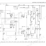
| Electrical - General Information, InfoView Diagnostics, Schematics and CAN Data Bus | 1037-1178 | General Information, InfoView Monitor Diagnostics, Electrical Schematics, CAN Data Bus Network |
| Electrical - Engine, Power Distribution, Cab, Hydraulic, Driveline, Header, Feeder, Threshing, Cleaning, Clean Grain, Crop Residue and Precision Farming Systems | 1179-1620 | Engine Systems, Power Distribution and Lighting, Cab Systems, Hydraulic Systems, Driveline Systems, Header Systems, Feeder Systems, Threshing Systems to Correct the Problem |
| Electrical - Connectors | 1621-1748 | Electrical Connectors, Connector X001 to X065, Cab Main and Console Connectors, Module Memory, Relay and Switch Terminations |
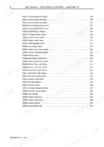
| Electrical - CCM1 and CCM2 Error Codes | 1749-2414 | CCM1 Error Codes, CCM2 Error Codes |
| Electrical - CCM3, Engine, HHC and ASP Fault Codes | 2415-2806 | CCM3 Error Codes, Engine Fault Codes, HHC Diagnostic Codes, ASP Fault Codes |
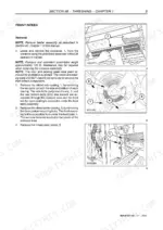
| Product Feeding (Section 60) | 2807-2974 | Feeder House, Feeder Drives, Stone Ejection System |
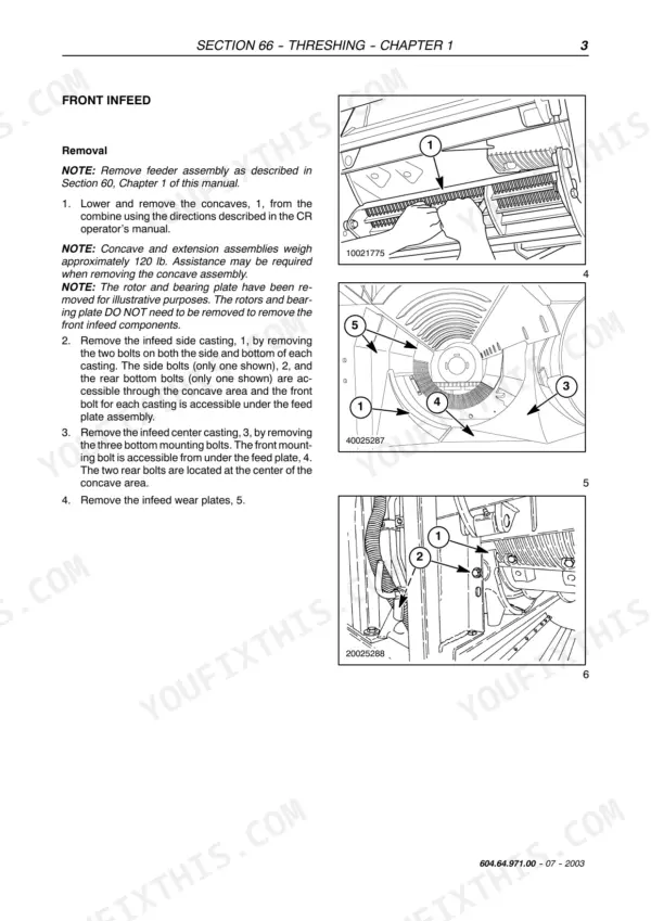
| Threshing (Section 66) | 2975-3112 | Rotor Chamber, Rotors, Main Threshing Drives |
| Separation (Section 72) | 3113-3124 | Discharge Beater |
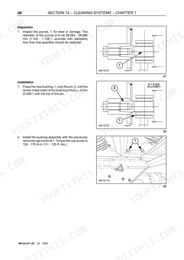
| Cleaning Systems (Section 74) | 3125-3332 | Cleaning Shoe Frame, Cleaning Shoe Drive, Cleaning Fan and Drives, Returns System |
| Grain Storage (Section 80) | 3333-3426 | Clean Grain Transport, Unloading System |
| Accessories (Section 88) | 3427-3458 | Straw Chopper, Chaff/Corn Spreader |
| Platform, Cab, Bodywork and Decals (Section 90) | 3459-3516 | Cab, Shielding |
Quick Reference Specifications
| Specification | Value | Page |
|---|---|---|
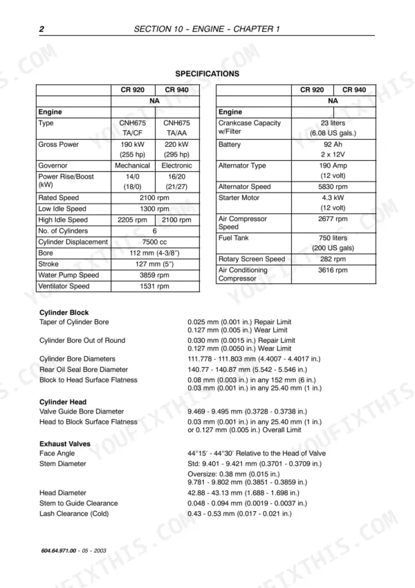
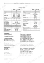
| Engine Type (CR 920) | CNH675 TA/CF | p. 62 |
| Engine Type (CR 940) | CNH675 TA/AA | p. 62 |
| Gross Power (CR 920) | 190 kW (255 hp) | p. 62 |
| Gross Power (CR 940) | 220 kW (295 hp) | p. 62 |
| Governor (CR 920) | Mechanical | p. 62 |
| Governor (CR 940) | Electronic | p. 62 |
| Rated Speed | 2100 rpm | p. 62 |
| Low Idle Speed | 1300 rpm | p. 62 |
| High Idle Speed (CR 920) | 2205 rpm | p. 62 |
| High Idle Speed (CR 940) | 2100 rpm | p. 62 |
| Cylinder Displacement | 7500 cc | p. 62 |
| Crankcase Capacity w/Filter | 23 liters (6.08 US gals.) | p. 62 |
| Battery | 92 Ah 2 x 12V | p. 62 |
| Alternator Type | 190 Amp (12 volt) | p. 62 |
| Starter Motor | 4.3 kW (12 volt) | p. 62 |
| Cylinder Block Taper of Cylinder Bore - Repair Limit | 0.025 mm (0.001 in.) | p. 62 |
| Cylinder Block Taper of Cylinder Bore - Wear Limit | 0.127 mm (0.005 in.) | p. 62 |
| Cylinder Bore Diameters | 111.778 - 111.803 mm (4.4007 - 4.4017 in.) | p. 62 |
| Rear Oil Seal Bore Diameter | 140.77 - 140.87 mm (5.542 - 5.546 in.) | p. 62 |
| Cylinder Head Valve Guide Bore Diameter | 9.469 - 9.495 mm (0.3728 - 0.3738 in.) | p. 62 |
New Holland CR920-CR980 Common Problems This Manual Covers
CCM error codes on the monitor with no explanation of what they mean or where to start
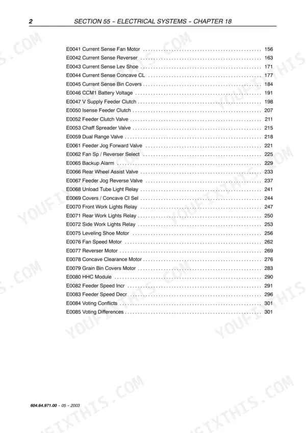
Section 55 chapters 18 through 23 list every CCM1, CCM2, CCM3, engine, HHC and ASP code with the circuit it monitors and what to check. Cross reference the Connectors and Electrical Schematics chapters to probe the actual wire instead of swapping parts on a guess.
Manual Section: Electrical - Fault Code Chapters (Section 55, ch. 18-23) p. 1749Turbocharger, injection regulation and head gasket trouble on higher-hour engines, especially the CR980
Start with the Engine Fault Codes chapter in Section 55 to confirm what the controller is actually complaining about, then work through Section 10 for the cooling system and fuel system procedures and the remove and replace sequence when the head or turbo has to come off.
Manual Section: Engine (Section 10) + Engine Fault Codes (Section 55) p. 1749Electric concave or separation grate adjustment fails mid-harvest
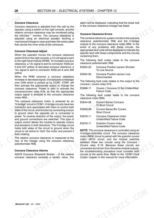
The Threshing Systems electrical chapter gives circuit descriptions and diagnostics for the adjustment actuators, and the schematics show every connector in the run. Most of these faults are a bad plug or dead actuator, both findable in an hour with a meter and the pinouts in the Connectors chapter.
Manual Section: Electrical - Threshing Systems + Schematics (Section 55) p. 1542Feeder house slugs, rattles and stops mid-field as the chain and lower feed roll wear
Section 60 covers the feeder house, feeder drives and stone ejection system, with disassembly, replacement and adjustment procedures for the chain and the lower feed roll. Set the chain tension by the factory procedure when you install it: an over-tight chain wears the feeder house floor, a slack one slugs the throat.
Manual Section: Product Feeding (Section 60) p. 2807Frequently Asked Questions
My combine is flashing an error code on the InfoView monitor. Will this manual tell me what it actually means?
Yes, and this is the main reason to own the book. Section 55 has dedicated chapters for CCM1, CCM2 and CCM3 error codes, plus engine fault codes, HHC diagnostic codes and ASP codes - over a thousand physical pages of listings (pages 1749-2806) tied to the circuit each code watches. You look up the number, trace the listed connectors on the schematics, and fix the cause. Clearing a code without fixing the circuit just brings it back on the next header engage. p. 1749
The electric concave or separation grate adjustment quit responding. Can I trace it with this manual?
This is a known sore spot on these machines, and it is almost always an actuator, a corroded connector or a CCM output - not the mechanism itself. The Threshing Systems electrical chapter walks the circuit, the Electrical Schematics chapter shows every wire in the run, and the Connectors chapter shows the plug faces so you probe the right pins. With a meter and this book it is an afternoon in the shop, not a dealer call during harvest. p. 1542
Does it cover the hydrostatic drive properly, including refilling after a pump swap?
Section 29 covers the hydrostatic system front to back: how it works, pressure testing and troubleshooting, pump and motor repair, the powered rear axle, and the filling and start-up procedure. That last one matters most - running a fresh pump without the proper fill and purge is how people wreck it in the first ten minutes. Having the factory procedure in writing is exactly what prevents that. p. 625
The CR980 runs the big 10.3L engine. Is that covered, or just the 7.5L?
The 7.5L New Holland engine (the CNH675 in the CR920 and CR940) gets the full treatment - remove and replace, cooling system, fuel system. The 7.8L and 10.3L get description of operation plus the shared engine module components: the engine gearbox and clutch pack in Section 14 are covered with full removal and rebuild for all five models, and engine fault codes for every variant live in Section 55. For a complete 10.3L teardown you would want the engine maker's book alongside this one. p. 227
3,516 pages is a lot. How do I actually find anything in it?
The PDF has native two-level bookmarks: click the section, then the chapter. The 17 sections follow New Holland's standard numbering (10 engine, 21 transmission, 29 hydrostatic, 55 electrical, 66 threshing and so on), so if you have used a NH book before you already know where things live. Torque figures sit inside the procedures where you need them - the transmission chapter, for example, gives the drive shaft nut at 150-170 N.m (111-125 ft. lbs.). p. 3






Reviews
There are no reviews yet.