

Part of the New Holland Repair Manuals.
The factory repair manual for New Holland DC75, DC85 and DC95 crawler dozers, publication 6-76640 dated 15/06/2004, bound as separately numbered chapter booklets (9890 through 9926). This is a teardown book: removal, installation, disassembly, assembly, exploded and sectional views across nine lettered sections.
It covers the hydrostatic power train with pressure tests and settings, primary and secondary hydraulic distribution, engine, fuel and cooling systems, service and parking brakes, steel tracks and rollers, planetary final drives, cab, ROPS and HVAC, the blade lift, tilt and angle circuits, and the ripper.
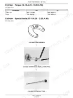
Machine-specific torque tables and wiring harness schematics are in here too. This is the book dealer techs pulled these machines apart with.
What's Inside This New Holland DC75 / DC85 / DC95 Repair Manual
| System | Pages | Key Topics |
|---|---|---|
| Introduction | 1-22 | Basic Instructions, Diagnostics, Hydraulic Contamination, General Specification, Torque Specifications, Straight Thread and Pipe Fittings, Conversion Factors |
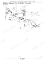
| Distribution Systems - Primary Hydraulic Power | 23-98 | Primary Hydraulic Power System, Stack Valve, Relief Valve, Oil Filter, Oil Cooler, Thermal Bypass Valve, Stack Valve Inlet Section |
| Distribution Systems - Secondary Hydraulic Power | 99-126 | Relief Valve, Stack Valve |
| Distribution Systems - Electrical Power | 127-262 | Electrical Power System, Battery, Fuse and Relay Box Fuse, Fuse and Relay Box Relay, Alternator, Wiring Harness, Alternator Drive System Belt |
| Power Production - Engine | 263-280 | Engine, Sensing System Speed Sensor |
| Power Production - Fuel and Injection System | 281-298 | Fuel Tank, Throttle Command Electrical Throttle, Throttle Command Mechanical Throttle, Throttle Command Electronic Throttle, Fuel Shut-Off Electrical Shut-Off, Sensing System Air Cleaner Restriction |
| Power Production - Engine Coolant System | 299-321 | Engine Coolant System, Radiator, Sensing System Coolant Temperature, Lubrication System, Sensing System Oil Pressure |
| Power Production - Starting System | 322-368 | Engine Starter, Starter Solenoid, Cold Start Aid, Start Control Start Switch, Drive Shaft |
| Power Train - Hydrostatic Transmission | 369-488 | Transmission Hydrostatic, Command Up/Down Switch, Pump, Motor, Diagnostic Connector, Command Inching Pedal, Pump Left Hand Pump |
| Travelling - Service Brake | 489-508 | Service BRAKE Hydraulic, Command, Control Valve |
| Travelling - Parking Brake | 509-524 | Command, Parking BRAKE Hydraulic, Sensing System Proximity Switch, Electrical Control Relay |
| Travelling - Wheels and Tracks | 525-647 | WHEELS and TRACKS Tracks, Steel Track Pad, Roller Lower Roller, Roller Upper Roller, Idler Wheel, Steel Track, Frame |
| Travelling - Final Drive | 648-744 | Final Drive, Housing Wheel Hub Housing, Gear Planetry Gearset, Gear Spur Gear, Housing Sandwich Housing, Housing Input Bearing Housing, Housing Drop Box |
| Body and Structure - User Controls and Seat | 745-778 | Seat Suspension System, Instrument Panel |
| Body and Structure - User Platform | 779-805 | ROPS, User Platform, Tilt System Pump, Wiper System Relay, Door, Window and Windscreen, Heat Command Fan Speed Switch, Ventilation System |
| Body and Structure - Air Conditioning | 806-861 | Compressor, Compressor Magnetic Clutch, Compressor Belt, Evaporator, Expansion Valve, Receiver/Drier, Sensing System Temperature Sensor |
| Body and Structure - Heating and Ventilation | 862-890 | Command, Condenser, Evaporator, Heater, Ventilation System Motor, Electrical Control, Electronic HVAC Control |
| Body and Structure - Safety and Security | 891-905 | Back Up Alarm Relay, Audio Alarm, Tool Support |
| Tool Positioning - Lifting | 906-949 | Cylinder, Command, Control Valve, Tool Support |
| Tool Positioning - Tilting | 950-984 | Cylinder, Command, Control Valve |
| Tool Positioning - Swinging | 985-1028 | Cylinder, Command, Control Valve, Command Lever |
| Tools and Couplers - Digging | 1029-1058 | Ripper, Ripper Cylinder, Ripper Bushing, Landscaping Dozer Blade, Cylinder |
Quick Reference Specifications
| Specification | Value | Page |
|---|---|---|
| Hydraulic reservoir refill capacity (DC75, DC85, DC95) | 75.7 L / 20 US gal | p. 23 |
| Type of hydraulic oil (DC75, DC85, DC95) | NEW HOLLAND AMBRA MULTI TRAN | p. 23 |
| Temperature of hydraulic oil when testing (DC75, DC85, DC95) | 52 - 79 °C / 125 - 175 °F | p. 23 |
| Hydraulic pump output (DC75, DC85, DC95) | 76.8 L/min at 207 bar at 2000 RPM / 20.3 US gpm at 3000 psi at 2000 RPM | p. 27 |
| Main relief valve pressure (All models at 2000 RPM) | 203 - 214 bar / 2950 - 3100 psi | p. 23 |
| Dozer blade lift time (ground level to full height) (DC75, DC85, DC95) | 2 seconds | p. 23 |
| Spool travel Neutral to pressure - lift, tilt and auxiliary (DC75, DC85, DC95) | 7.9 mm / 0.31 in | p. 12 |
| Spool travel Neutral to pressure - angle section (DC75, DC85, DC95) | 6.6 mm / 0.26 in | p. 26 |
| Spool travel Neutral to float - lift (DC75, DC85, DC95) | 13.5 mm / 0.53 in | p. 26 |
| Main relief valve (calibration) (DC75, DC85, DC95) | 203 - 214 bar / 2950 - 3100 psi | p. 23 |
| Circuit relief valves tested with hand pump (calibration) (DC75, DC85, DC95) | 214 - 227 bar / 3100 - 3300 psi | p. 23 |
New Holland DC75 / DC85 / DC95 Common Problems This Manual Covers
Blade drifts down or won't hold grade under load
Blade creep almost always comes down to worn piston seals or a leaking control valve section. The Tool Positioning - Lifting section covers cylinder removal, disassembly, seal replacement and assembly, plus the lift control valve, so you can reseal the cylinders and rule out the valve before blaming the pump. Tilt and angle cylinders get the same treatment in their own sections.
Manual Section: Tool Positioning - Lifting p. 369Thrown tracks, fast track wear or a sloppy undercarriage
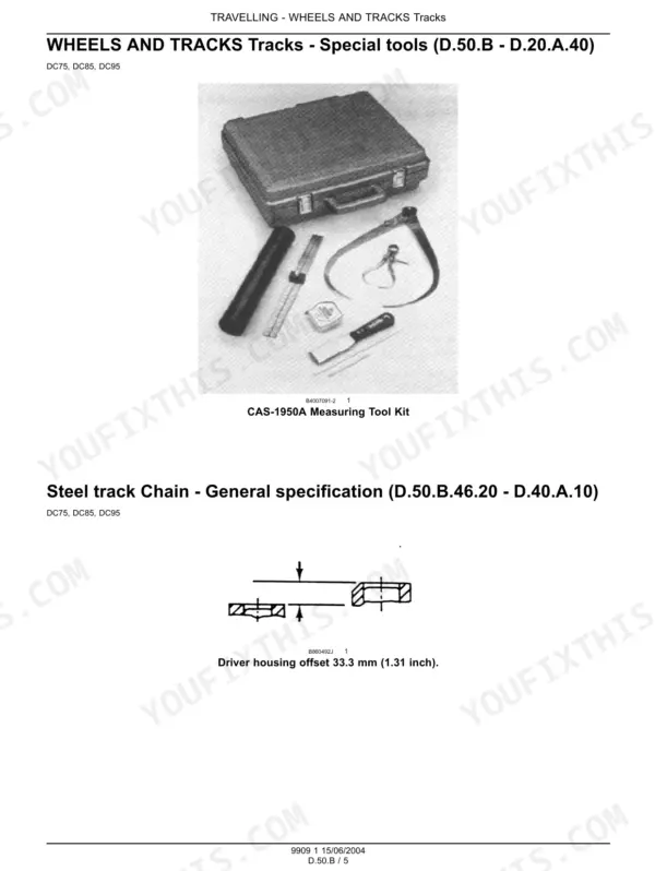
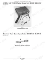
Undercarriage is the money pit on any crawler, and these three are no exception. The Travelling - Wheels and Tracks section covers steel tracks, track pads, lower and upper rollers, idler wheels and the track frame with removal, installation and inspection steps, so you can measure wear and replace only what is actually finished.
Manual Section: Travelling - Wheels and Tracks p. 127Grinding, noise or loss of drive on one side
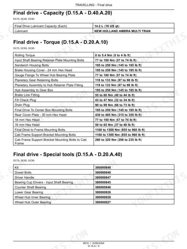
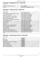
A dead or noisy side usually means trouble in the planetary gearset or spur gear. The Travelling - Final Drive section breaks down the wheel hub housing, planetary gearset, sandwich housing, input bearing housing and drop box with exploded views, so you can open the drive, find the damaged gear and rebuild it instead of pricing a complete assembly.
Manual Section: Travelling - Final Drive p. 525No-start, intermittent starting or phantom temperature and oil pressure warnings
On these dozers that is usually a switch, relay, sender or harness fault, not the engine. Work through the Distribution Systems - Electrical Power section: battery, fuse and relay box, alternator and the wiring harness schematics let you trace the circuit instead of throwing parts at it. The coolant temperature and oil pressure senders are covered under Power Production.
Manual Section: Distribution Systems - Electrical Power p. 906Frequently Asked Questions
Does it have the torque specs for the hydrostatic transmission and drive line?
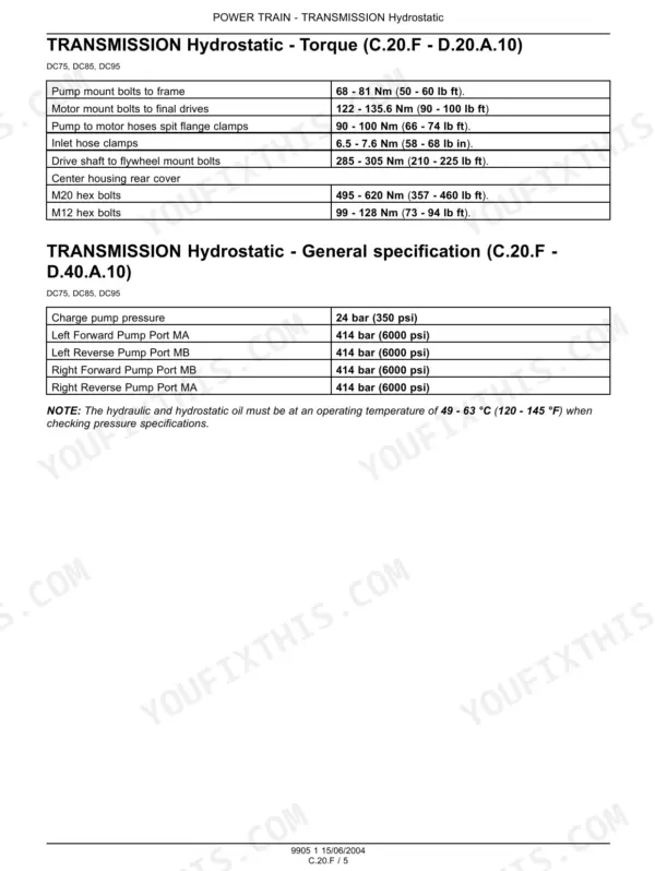
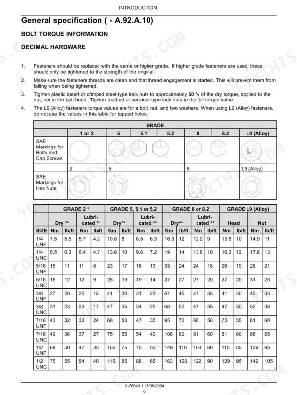
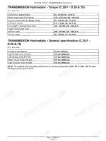
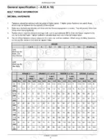
Yes, with real numbers. Pump mount bolts to the frame run 68-81 Nm (50-60 lb ft), motor mount bolts to the final drives 122-135.6 Nm (90-100 lb ft), drive shaft to flywheel bolts 285-305 Nm (210-225 lb ft), and the M20 hex bolts 495-620 Nm (357-460 lb ft). The introduction also carries a general torque chart plus straight thread and pipe fitting torques. p. 369
Can I diagnose weak travel or one dead side of the hydrostatic drive with this book?
That is what it is built for. It gives you the pressure specs to test against: charge pump at 24 bar (350 psi), forward and reverse pump ports at 414 bar (6000 psi), and it tells you the oil has to be at 49-63 C (120-145 F) before any reading counts. From there it walks pump and motor removal, disassembly and assembly, including the left hand pump and the inching pedal. p. 172
Does it include wiring diagrams and hydraulic schematics?
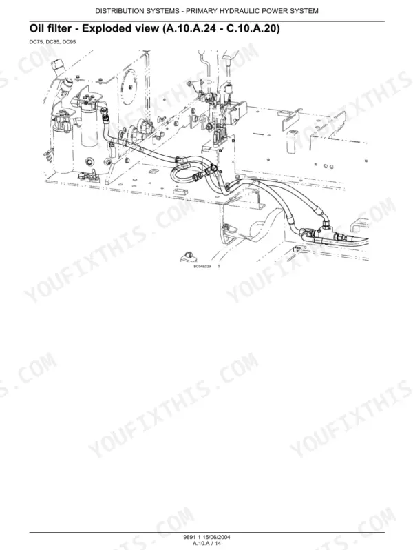
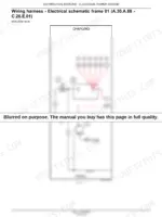
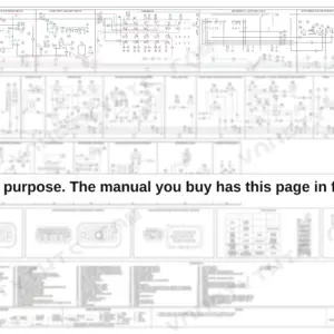
Electrical yes: the wiring harness coverage includes schematics for tracing circuits, fuses, relays and the alternator system. On the hydraulic side, be clear about what you are buying: coverage is component level, with stack valve, relief valve, filter and cooler service plus pressure tests and settings. There is no single full hydraulic circuit diagram, so buy it for teardown and testing, not for tracing the whole oil path on one sheet. p. 23
How do I look up error codes for a DC75, DC85 or DC95?
You mostly don't, because these 2004 machines are not fault-code machines. The manual troubleshoots the old way: pressure gauges on the hydrostatic circuit, visual inspection, electrical checks through the harness schematics, and the diagnostic connector on the transmission. If a warning light is on, the book helps you test the sender and circuit behind it rather than hand you a code table. p. 10
Which machines does this manual cover?
New Holland DC75, DC85 and DC95 crawler dozers. It is publication 6-76640, dated 15/06/2004, and the three model volumes carry their own numbers: 9890 for the DC75, 9893 for the DC85 and 9905 for the DC95. All three share the same layout, so one book serves a mixed fleet. p. 17





Reviews
There are no reviews yet.