

Part of the New Holland Repair Manuals.
The factory service set for the New Holland LV80 Tractor Loader Landscaper, bound from separately numbered section booklets 86641267 through 86641272, with issue dates printed on each - one reads Issued Sept 02. The schematic sheets at the back state they apply from P.I.N. LLV001378 and after.
You get the 439 Diesel Engine section with special tools and crankcase specifications, fuel system and injection pump gear work, a full electrical section on relays, senders, charging and cranking circuits, steering and front axle hub service, power train, brakes with a bleed procedure, hydraulics including the Glide Ride accumulator and solenoid, and mounted equipment with A/C recovery.
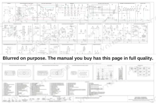
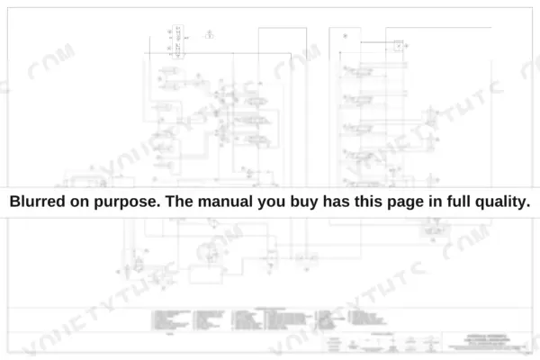
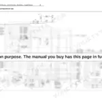
The payoff is at the back: two oversized fold-out sheets, a complete electrical schematic in numbered circuit frames and a complete hydraulic schematic with a full component legend.
What's Inside This New Holland LV80 Manual
| System | Pages | Key Topics |
|---|---|---|
| Table of Contents and Introduction | 1-13 | Section Booklets 86641267 to 86641272, Proprietary Notice, General Information |
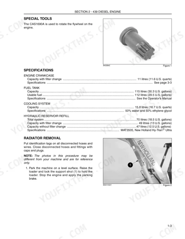
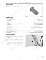
| 439 Diesel Engine | 14-344 | Special Tools, Engine Crankcase Specifications, Fuel Tank, Cooling System, Hydraulic Reservoir Specifications, Radiator Removal |
| Fuel System | 345-454 | Injection Pump Gear Removal and Installation, Fuel System General Information |
| Electrical System | 455-594 | Relays, Switches, Senders, Solenoids, Battery Maintenance, Charging and Cranking Circuits, Fuse Block, Instrument Cluster |
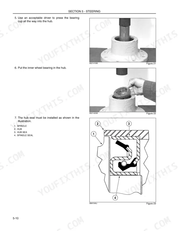
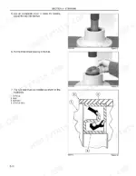
| Steering and Front Axles | 595-775 | Bearing Cup, Inner and Outer Wheel Bearings, Hub Seal, Spindle Seal, Hub Installation |
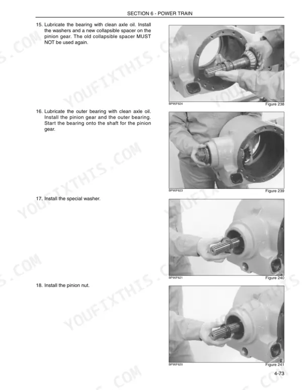
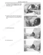
| Power Train | 776-1075 | Pinion Gear Assembly, Differential, Differential Lock Fork |
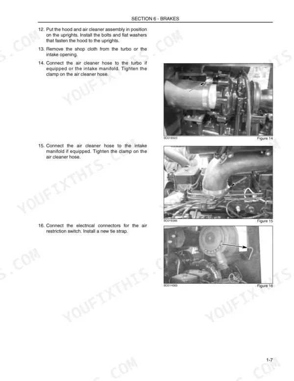
| Brakes | 1076-1103 | Master Cylinder Installation, Removing Air From the Brake System, Air Cleaner Assembly, Exhaust Pipe |
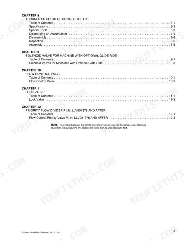
| Hydraulic System | 1104-1324 | Accumulator for Optional Glide Ride, Glide Ride Solenoid Valve, Flow Control Valve, Lock Valve, Priority Flow Divider |
| Mounted Equipment | 1325-1437 | Safety Procedures, Special Tools, Operation, Troubleshooting, System Checks, A-C Recovery and Charging Station |
| Hydraulic and Electrical Schematic Sheets (6-77000) | 1438-1439 | Full Electrical Schematic in 23 Circuit Frames, Full Hydraulic Schematic, Fuse and Relay Location, Harness Connector Pin Maps, Wire Colour Code Key |
Quick Reference Specifications
| Specification | Value | Page |
|---|---|---|
| Engine Crankcase Capacity with filter change | 11 litres (11.6 U.S. quarts) | |
| Fuel Tank Capacity | 115 litres (30.3 U.S. gallons) | |
| Fuel Tank Usable fuel | 112 litres (29.5 U.S. gallons) | |
| Cooling System Capacity | 15.8 litres (16.7 U.S. quarts) | |
| Cooling System Specifications | 50% water and 50% ethylene glycol | |
| Hydraulic Reservoir Refill Total system | 70 litres (18.5 U.S. gallons) | |
| Hydraulic Reservoir Refill Capacity with filter change | 49 litres (13 U.S. gallons) | |
| Hydraulic Reservoir Refill Capacity without filter change | 47 litres (12.5 U.S. gallons) | |
| Hydraulic Reservoir Refill Specifications | MAT3505, New Holland Hy-Tran® Ultra | |
| Full throttle - no load | 2350 to 2500 rpm | |
| Full throttle - full load | 2200 rpm | |
| Idle speed | 900 to 1100 rpm | |
| Loader hydraulic stall | 2100 to 2350 rpm | |
| Torque converter stall | 1850 to 2350 rpm | |
| Combined stall | 1040 to 1600 rpm |
New Holland LV80 Common Problems This Manual Covers
Engine vibration, harsh idle, or visible movement at the motor mounts
Mounts are a known wear item on these machines, and the fix is straightforward once you have access. The 439 Diesel Engine booklet 86641267 lists the special tools and gives the radiator removal procedure you will need to open up the front of the engine bay for the job.
Manual Section: 439 Diesel Engine (booklet 86641267) p. 1438Hard shifting, sloppy gear selection, or a differential lock that will not engage
Shift complaints usually trace to worn linkage, and a dead diff lock points at the fork. The Power Train booklet 86641271 walks through the pinion gear assembly, the differential, and the differential lock fork so you can measure the wear and rebuild it instead of guessing at the lever.
Manual Section: Power Train (booklet 86641271) p. 1104Cylinder drift, weak lift or tilt, or a Glide Ride circuit acting up
Drift is almost never the pump. Work through the Hydraulic System section, which covers the lock valve, flow control valve, priority flow divider, and the Glide Ride accumulator and solenoid valve, then use the fold-out hydraulic schematic to isolate which circuit is bleeding pressure before you buy a single seal.
Manual Section: Hydraulic System p. 776No crank, dead gauges, or an intermittent electrical fault
Start at the fuse block and relays before condemning the starter or alternator. The Electrical System section covers the charging and cranking circuits, relays, switches, senders, and instrument cluster, and schematic sheet 6-77000 breaks the whole machine into numbered circuit frames with connector pin maps and a wire colour code key.
Manual Section: Electrical System / Schematic Sheets (6-77000) p. 595Frequently Asked Questions
Does this manual include a full wiring diagram for the LV80?
Yes, and it is the best part of the book. Bound at the back is an oversized fold-out electrical schematic split into numbered circuit frames, with fuse and relay locations, harness connector pin maps, and a wire colour code key. It covers charging, cranking, keyswitch power relays, ether start, instrument cluster and alarm, return-to-dig, wipers, blower and air conditioning, lamps, horn, 4WD circuit, differential lock, and power plugs. Both sheets are also orderable separately as part number 6-77000. p. 1439
My loader drifts down and the lift feels weak. Will this manual actually help me find it?
Yes. The Hydraulic System section covers the lock valve, flow control valve, priority flow divider, and the Glide Ride accumulator and solenoid valve, which are the usual suspects along with tired cylinder seals. Pair that with the fold-out hydraulic schematic, which maps the reservoir, pump, loader control valve with lift, tilt, clam and auxiliary spools, and relief valves, so you can trace exactly where pressure is bleeding off instead of swapping parts blind. p. 1438
Can I pull fault codes or do a reset procedure with this manual?
No, and that is honest, not a gap in the book. This generation of LV80 is not diagnosed through plug-in fault codes. Troubleshooting is done the old way: system checks in each section and a test meter on the circuits shown in the schematic frames. If a seller promises you code charts and calibration resets for this machine, be skeptical. p. 14
How do I know this covers my machine?
The schematic sheets name the machine LV80 LOADER LANDSCAPER and state they apply from P.I.N. LLV001378 and after, so check the product identification number on your machine. The set is bound from section booklets 86641267 through 86641272, each carrying its own issue date, one printed Issued Sept 02. p. 1104
The brake pedal is soft. Does the manual cover bleeding the system?
Yes. The Brakes booklet 86641272 includes Removing Air From the Brake System and master cylinder installation, which is what you need after any hydraulic brake work on this machine. A soft pedal after a master cylinder swap is nearly always trapped air, so follow the printed sequence rather than pumping the pedal and hoping. p. 1





Reviews
There are no reviews yet.