


Part of the Yanmar Repair Manuals.
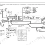
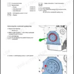
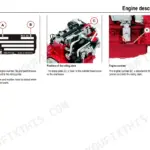
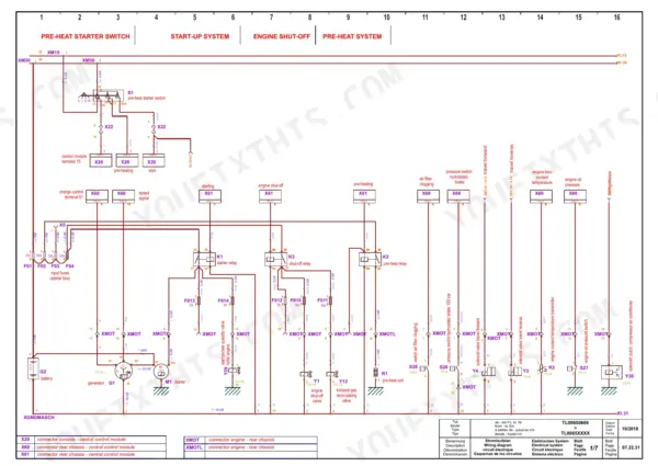
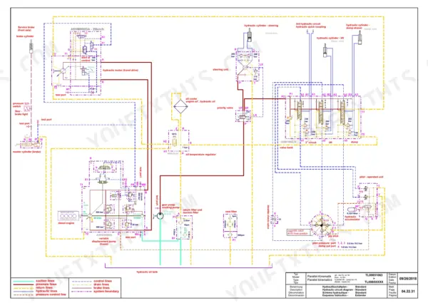
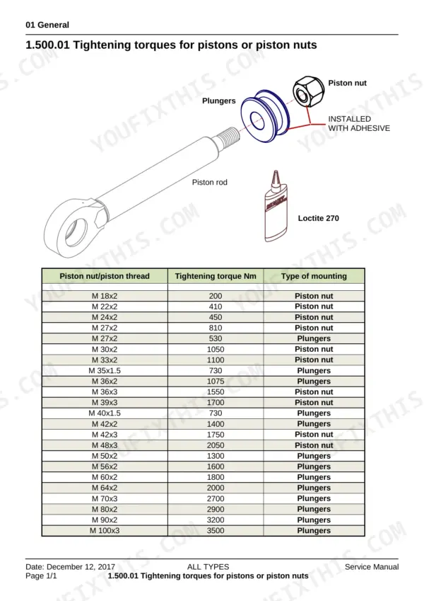
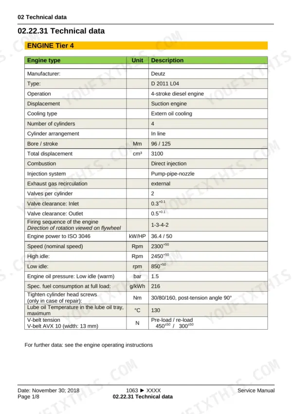
Every one of the 523 pages in this Yanmar V65 Wheel Loader Service Manual targets one machine: your V65, from Tier 4 diesel internals to parallel-kinematic travel hydraulics. Inside: full wiring diagrams with cable colors, fuse and relay assignments, and control module pinouts, plus hydraulic circuit diagrams for both Parallel-Kinematic and Z-Kinematic standard configurations. You also get setting instructions for the Hydromatik travel system, a dedicated calibration section, error codes, step-by-step repair procedures for hydraulic fittings and cab components, and a complete maintenance inspection plan. Torque the M 18x2 piston nut to 200 Nm; swap the fuel filter every 500 hours. No more chasing a torque value through three different forums. Bookmarked and keyword-searchable; grab it on your tablet and walk straight to the machine.
What's Inside This Manual
| System | Pages | Key Topics |
|---|---|---|
| General | 3-46 | Foreword / User Instructions, Safety and Accident Prevention, Description of Safety Signs, Tightening Torques of Pistons or Piston Nuts, Pictograms, Units |
| Technical Data | 47-58 | Engine Tier 4, Electrical System, Steering- / Slew System, Pressure Values and Settings, Braking System, Fluid Capacities |
| Diesel Engine | 59-400 | Engine Description, Lubricating Oil Schematic, Fuel Schematic, Coolant Schematic, Electrics/Electronics, Maintenance Schedule |
| Hydraulics | 401-406 | Hydraulic Circuit Diagram: Parallel-Kinematic Standard, Hydraulic Circuit Diagram: Z-Kinematic Standard |
| Setting Instructions | 407-444 | General Setting Instructions, Hydromatik Tightening Values, Travel Hydraulics – Setting Instructions, Valve Description HDM19WL, Service and Parking Brake |
| Functional Description | 445-450 | Suction and Return Filter, Pilot Control Device 4TH6 |
| Electrics | 451-464 | Cable Colors, Read Links in Electric Schematics, Links on the Control Module and Display, Wiring Diagrams, Fuse and Relay Assignment |
| Maintenance | 465-474 | Specification for Fuels, Lubricants and Coolants, Inspection Plan |
| Operation | 475-480 | Proportional Actuation, 3rd Hydraulic Control Circuit, Finger-Tip-Control, Float Position Functionality, Control Lever, Potentiometer |
| Options | 481-484 | Control Block, Ride Control Valve, Hydraulic Cylinders, Accumulator, Solenoid Valves |
| Repair Instructions | 485-500 | Fitting Hydraulic Screw Connections, Adhesive Kit, Cab Windows, Cutting Ring Fittings, Taper Coupling (Dko), Swivel Nut |
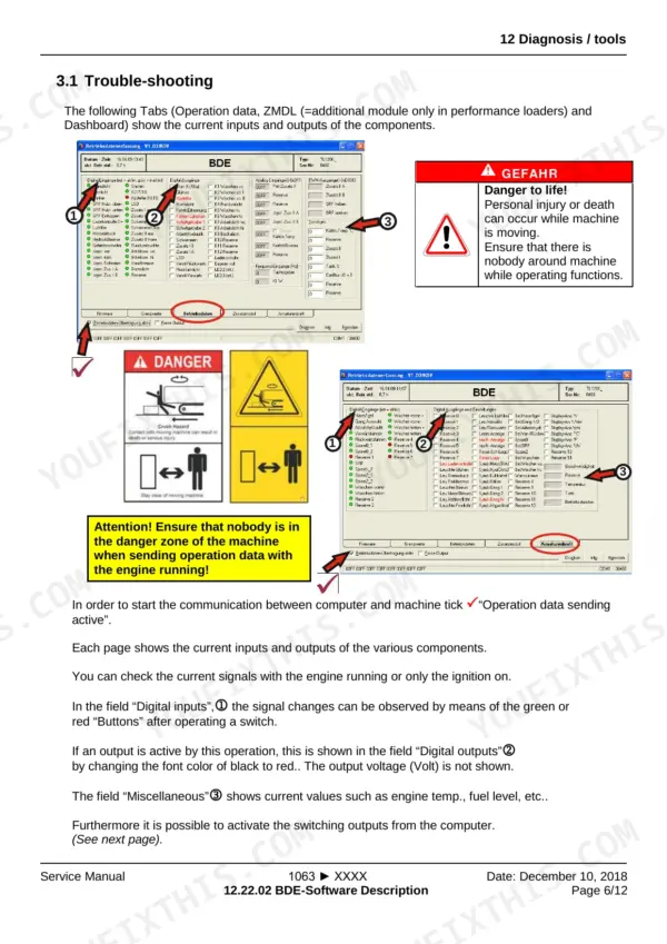
| Diagnosis / Tools | 501-523 | Foreword / User Instructions, Safety and Accident Prevention, Safety Signs, Tightening Torques of Pistons or Piston Nuts, Tightening Torques of Guide Bushings, Pictograms |
Quick Reference Specifications
| Specification | Value | Page |
|---|---|---|
| Tightening torque for M 18x2 piston nut | 200 Nm | p. 25 |
| Control module hardware reset | Switch off ignition, wait 5 sec, then switch on ignition again | p. 518 |
| Standard battery | 12 / 100 / 900 (DIN EN 50342) | p. 50 |
| Fuel filter replacement interval | every 500 hours | p. 471 |
| Tightening torque for fuel filter console/full load stop to crankcase | 22 Nm | p. 412 |
| Hydraulic oil return suction filter replacement interval | every 100 hours | p. 471 |
| Tightening torque for lubricating oil cooler on oil filter console | 13 Nm | p. 2 |
| Straight pipe end dimension target | > double the nut height | p. 491 |
| Tightening torque for L6 M12 x 1.5 DKO hose | 18 Nm | p. 25 |
| General instruction for sealing components | generally replacing sealing components during each repair should be a matter of course | p. 5 |
| Cutting ring incision result | 100% cutting ring incision | p. 488 |
| Cooling fins cleaning interval | shorten cleaning intervals in case of visible dust | p. 471 |