
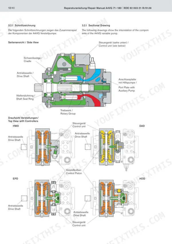
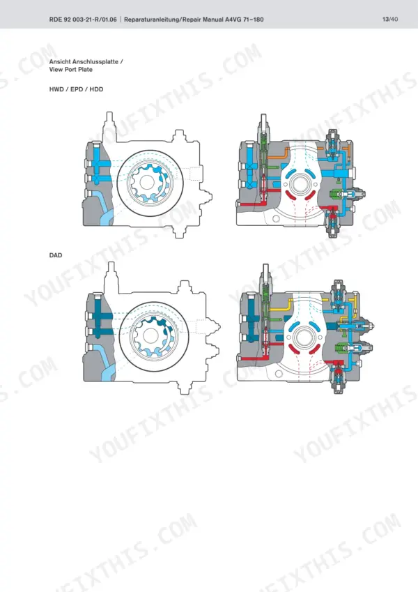
Resealing a Bosch Rexroth A4VG variable pump without shipping it out for a rebuild is the job the 42 pages of repair manual RDE 92 003-21-R/01.06 are written for, across four nominal sizes of the series. Most of the book goes to exchanging external assembly groups on the A4VG 71, 90, 125 and 180: the shaft seal, positioning piston covers, low- and high-pressure valves, pressure cut-off, control valve O-rings, the backing pump and the complete control unit. A closing section walks you through checking charge pressure, high pressure, and mechanical and hydraulic zero stroke before the pump goes back into service. Run the high-pressure valves down to 150 Nm on NG 71 and 90 or 200 Nm on NG 125 and 180, then hold the control unit screws at 10.4 Nm. A weeping shaft seal can leave a machine parked for days. The PDF is bookmarked and text-searchable, so you reach the right page quickly and your machine can be moving again the same shift.
What's Inside This Bosch Rexroth A4VG 71-180 Series 32 Repair Manual
| System | Pages | Key Topics |
|---|---|---|
| About This Manual | 2-6 | Contents, Validity of This Manual, Important Documents, Danger Labels and Pictograms |
| Safety | 7-10 | Basic Safety Information, Requirements on the Personnel |
| Product Description | 11-14 | Name Plate, Functional Description, Technical Data |
| Exchanging the Shaft Seal | 16-17 | Mounting Sleeve, Circlip, Shaft Seal, Drive Shaft |
| Exchanging Seals | 18-23 | Positioning Piston Covers, Low-Pressure Valve, High-Pressure Valve, Pressure Cut-Off, Control Valve, O-Rings |
| Exchanging the Backing Pump | 24-25 | Auxiliary Pump, Cover, O-Rings, Fixing Plugs, Port Plate |
| Exchanging the Control Unit | 26-32 | Control Unit, Gasket, O-Rings, Fastening Screws, Auxiliary Screws, Cover |
| Checking | 33-42 | Checking Low Pressure (Charge Pressure), Checking High Pressure, Checking the Mechanical Zero Stroke, Checking the Hydraulic Zero Stroke |
Quick Reference Specifications
| Specification | Value | Page |
|---|---|---|
| All Models | ||
| Control unit fastening screw (f) tightening torque | 10.4 Nm | p. 30 |
| Control unit assembly screw (f) tightening torque | 10.4 Nm | p. 30 |
| Low pressure valve tightening torque | 70 Nm | p. 23 |
| Pressure cut-off locking screw tightening torque | 35 Nm | p. 24 |
| Pressure cut-off sealing nut tightening torque | 25 Nm | p. 24 |
| Control valve tightening torque | 50 Nm | p. 25 |
| Pole tube tightening torque | 19 Nm | p. 28 |
| Control unit solenoid tightening torque | 5+1 Nm | p. 28 |
| Control unit fifth screw tightening torque | 10.4 Nm | p. 30 |
| A4VG 71, A4VG 90 | ||
| High-pressure valve tightening torque (NG 71-90) | 150 Nm | p. 24 |
| A4VG 125, A4VG 180 | ||
| High-pressure valve tightening torque (NG 125, 180) | 200 Nm | p. 24 |
| A4VG 90, A4VG 125, A4VG 180 | ||
| Control unit assembly screws tightening torque (NG 90-180) | 10.4 Nm | p. 32 |
Bosch Rexroth A4VG 71-180 Series 32 Common Problems This Manual Covers
Bosch Rexroth A4VG 71-180 variable pump shaft seal leaking hydraulic oil around the drive shaft
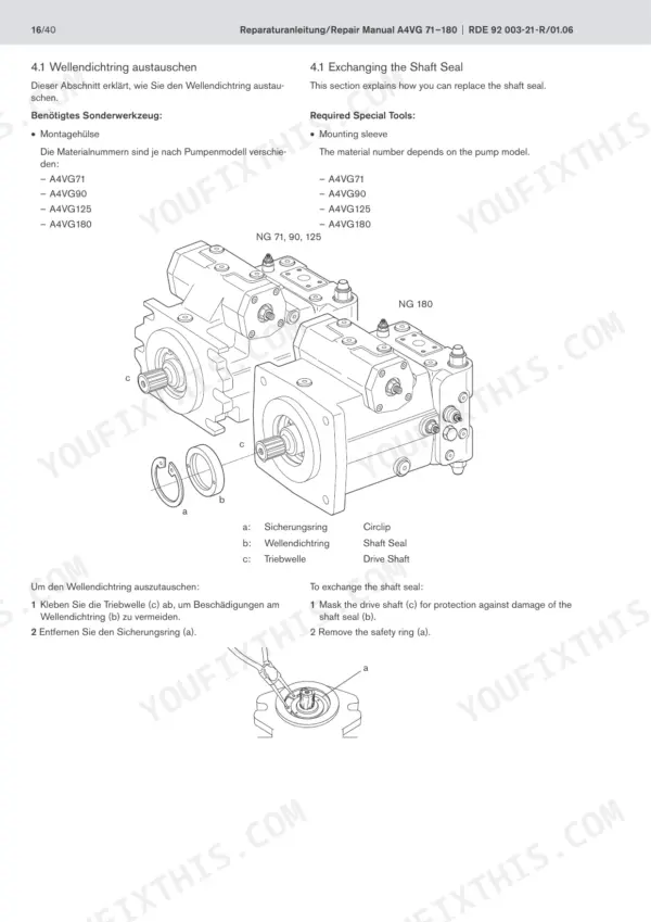
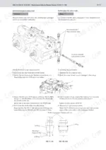
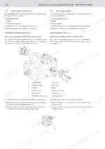
Verify the system is shut down and the engine cannot be switched on, as page 9 requires. Mask the drive shaft, remove the circlip, and pull the old seal out with tapping screws set in its rubber lined holes and a pair of pliers, following page 18. Grease between the seal and dust lip, press the new seal to its stop with the correct mounting sleeve, then lock the circlip into its slot.
Manual Section: Exchanging the Shaft Seal p. 18Positioning piston cover O-rings leaking oil at the left or right cover
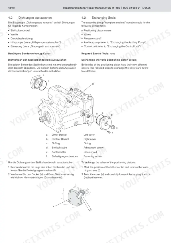
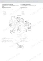
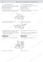
Measure and record dimension X of the right cover's counter nut before removal, and mark both cover positions, following page 20. Remove the old O-rings and inspect the grooves and housing for wear and dirt. Hold the adjustment screw while tightening the counter nut, and verify X again. Then check the mechanical zero stroke after installation, blocking the machinery first as page 37 requires.
Manual Section: Exchanging Seals (Positioning piston covers) p. 20Low-pressure valve O-rings seeping oil at the valve threads on the pump housing
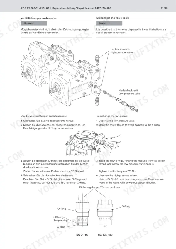
Clean the area thoroughly before opening the connection, and don't use rags that shed threads, per page 17. Unscrew the low-pressure valve and mask the threads so the new O-rings don't get cut. Fit the new O-rings, then remove the masking. Torque the valve to 70 Nm following page 23.
Manual Section: Exchanging Seals (Valves) p. 23Pressure cut-off leaking oil past the sealing nut and locking screw O-ring
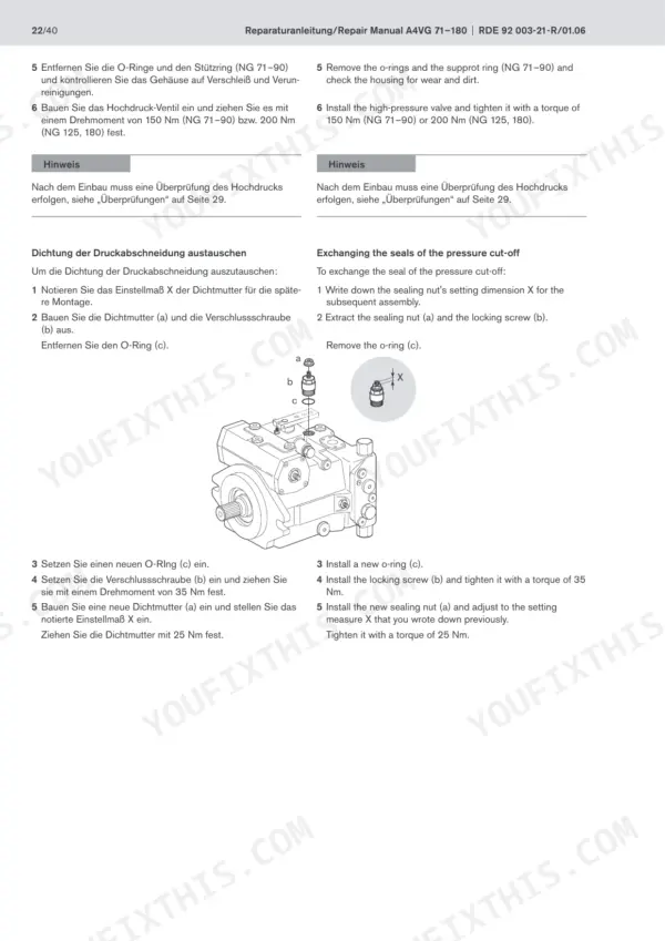
Measure and record the sealing nut's setting dimension X before you touch it, following page 24. Remove the sealing nut and locking screw, replace the O-ring, and torque the locking screw to 35 Nm. Install a new sealing nut, set it back to dimension X, and torque it to 25 Nm.
Manual Section: Exchanging Seals (Pressure cut-off) p. 24Auxiliary pump behind its bolted cover showing worn parts and dirt contamination
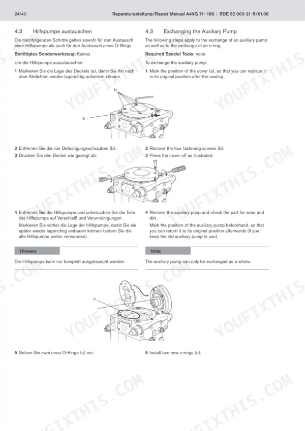
Mark the cover position, remove the four fastening screws, then press the cover off and inspect the auxiliary pump for wear and dirt. It can only be replaced as a complete unit. Fit two new O-rings, install the pump with its chamfered side facing the cover, and press the fixing plugs into the port plate bores, per page 27.
Manual Section: Exchanging the Auxiliary Pump p. 27Control unit leaking oil past the O-ring and gasket at the housing sealing surfaces
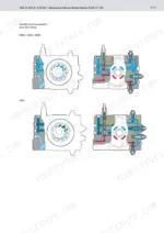
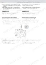
Remove the five fastening screws on NG 71 units and press the control unit off following page 29. Fit a new O-ring and gasket, and check the sealing surfaces for wear and dirt. If they are damaged, replace the control unit, since it is only exchanged complete. Torque the fastening screws to 10.4 Nm per page 30.
Manual Section: Exchanging the Control Unit p. 29Frequently Asked Questions
How do you adjust the A4VG pressure cut-off and zero-pressure setting?
To adjust the pressure cut-off, note the setting dimension X, remove the sealing nut (a) and locking screw (b), install a new O-ring (c), and tighten the locking screw to 35 Nm. Reinstall the sealing nut and adjust to the previously noted dimension X, then tighten the nut to 25 Nm. p. 24
What is the torque specification for the low-pressure valve on the Bosch Rexroth A4VG 71-180 Series 32?
When reinstalling the low-pressure valve after replacing the O-rings, it must be tightened to a torque of 70 Nm. p. 23
What is the torque specification for the high-pressure valve on the Bosch Rexroth A4VG 71-180 Series 32?
The high-pressure valve must be tightened to 150 Nm for NG 71–90 models, or 200 Nm for NG 125 and 180 models. p. 24
What is the torque spec for the control unit fastening screws on the Bosch Rexroth A4VG 71-180 Series 32?
For the NG 71 model, the fifth fastening screw must be tightened to 10.4 Nm, and the other four screws should be tightened crosswise to the same torque. p. 30
What is the tightening torque for the pole tube on the control unit of the Bosch Rexroth A4VG 71-180 Series 32?
The pole tube on the control unit must be tightened to a torque of 19 Nm. p. 28
Is this Bosch Rexroth A4VG 71 manual a PDF I download?
One searchable PDF covering 42 pages, delivered instantly. No disc, no shipping, no waiting on the post.
Can I print just the pages I need from this Bosch Rexroth A4VG 71 manual?
Yes. It prints from any PDF reader, so run off the pages you need for your own repair work.
Reviews
There are no reviews yet.