
![John Deere 5-750 5-754 5-800 5-804 5-850 5-854 5-900 5-950 Repair Manual [Tractors]](https://youfixthis.com/wp-content/uploads/2012/02/Manual_Download-300x300.jpg)
Part of the John Deere Repair Manuals.
All 402 pages of this John Deere 5055E Repair Manual PDF (OEM #TM801719) target one job: returning your 5055E, 5065E, 5075E, 5078E, 5085E, or 5090E tractor to factory spec. Inside you get torque tables for metric and SAE bolt values plus face seal fitting specs at both standard and high pressure, alongside step-by-step rebuild procedures for the TSS transmission, LUK clutch, differential, final drives, steering valve, brakes, and Bosch hydraulic pump. Exploded views throughout give you parts orientation before you touch a wrench, and a fluid capacities section tells you exactly what goes back in. Torque the hydraulic pump attaching bolts to 120 N.m, then confirm PTO clutch disk thickness falls between 6.6 and 7.6 mm before buttoning up the clutch housing. Your machine's down and the dealer wants three weeks. Search by keyword, jump by bookmark, pull it up on your tablet at the bench, and start wrenching with factory numbers in front of you.
Complete the set for your 5055E-5090E
- Operation & Tests: John Deere 5055E, 5065E and 5075E Tractor Diagnostic and Tests Manual
Other editions of this manual
What's Inside This John Deere 5055E-5090E Repair Manual
| System | Pages | Key Topics |
|---|---|---|
| General Information | 6-41 | Group 05 - Safety (Recognize Safety Information, Understand Signal Words, Follow Safety Instructions, Handle Fluids Safely, Avoid Fires, Prevent Battery Explosions, Prepare for Emergencies, Prevent Acid Burns, Service Cooling System Safely, Handle Chemical Products Safely, Avoid High-Pressure Fluids, Park Machine Safely, Support Machine Adequately, Wear Protective Clothing, Work in Clean Area, Service Machines Safely, Work in Ventilated Area, Illuminate Work Area Safely, Replace Safety Signs, Use Proper Lifting Equipment, Keep ROPS Installed Properly, Service Tires Safely, Avoid Harmful Asbestos Dust, Avoid Heating Near Pressurized Fluid Lines, Remove Paint Before Welding or Heating, Use Proper Tools, Dispose of Waste Properly, Live with Safety) |
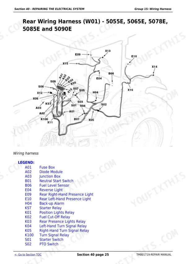
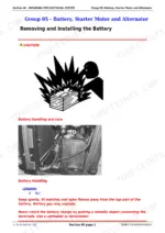
| Repairing the Electrical System | 42-74 | Group 05 - Battery, Starter Motor and Alternator (Removing and Installing the Battery, Removing and Installing the Starter Motor, Replacing Alternator) |
| Group 05 - Clutch Housing, Tss Transmission | 75-87 | Practice Safe Maintenance, Use Proper Tools, Special Tool, Other Material |
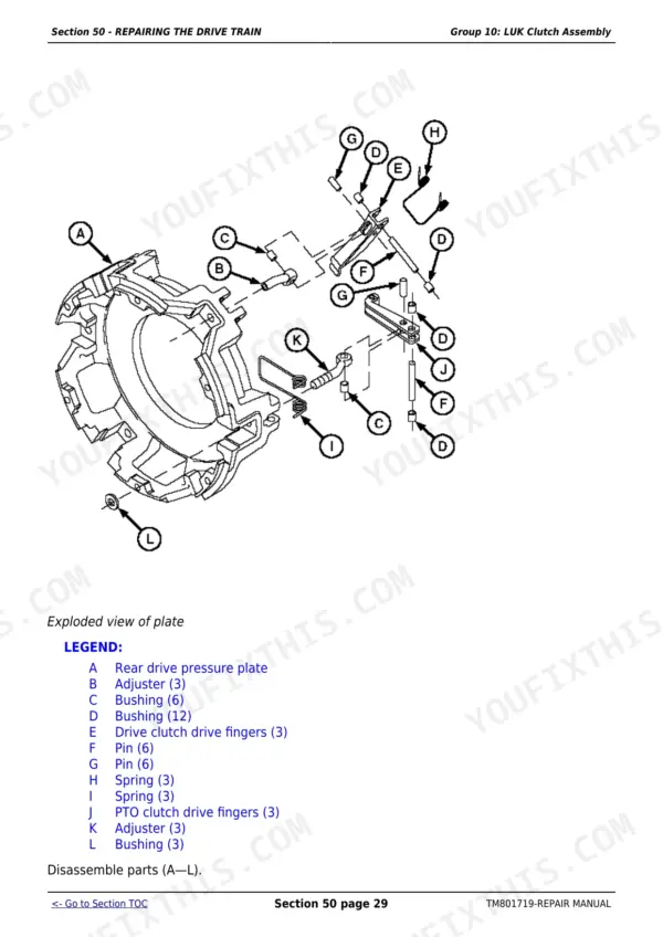
| Group 10 - Luk Clutch Assembly | 88-118 | Special Tools, Specifications, Clutch Housing Seals, Removing and Installing Clutch Assembly |
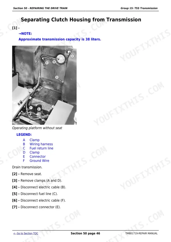
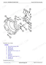
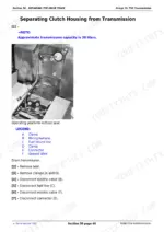
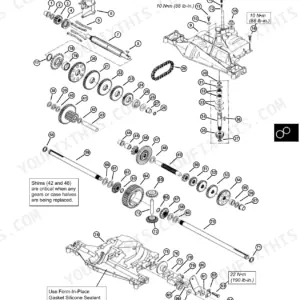
| Group 15 - Tss Transmission | 119-215 | Special Tool, Other Material, Separating Clutch Housing From Transmission, Installing Clutch Housing to Transmission |
| Group 20 - PTO Drive Shaft | 216-228 | Other Material, Inspection and Repair of PTO Lever and Link, Removing and Installing Standard Rear PTO Drive Shaft Assembly (Standard and 540/540E), Removing |
| Group 25 - Differential | 229-249 | Essential or Special Tools, Removing and Installing Differential Assembly, Disassembly, Inspection and Assembling of Differential Assembly |
| Group 30 - Final Drives | 250-265 | Special or Essential Tools, Final Drive Turning Tool, Other Material, Removing and Installing Final Drive Assembly |
| Group 35 - Front-Wheel Drive Actuation | 266-284 | Special or Essential Tools, Other Material, Inspecting and Repairing PTO Lever and Linkage, Removing and Installing PTO Housing |
| Group 40 - Creeper Transmission | 285-291 | Removing and Installing Creeper Transmission, Disassembling, Inspecting and Assembling Creeper Transmission, Final Considerations, Bleeding Brakes |
| Repairing Steering and Brakes | 292-327 | Group 05 - Repairing the Steering (Other Material, Special Tool, Replacement Kits, Removing and Installing Steering Valve and Column, Disassembling and Inspecting Steering Valve, Assembling Steering Valve, Inspecting and Replacing Steering Hydraulic Lines) |
| Hydraulic Repair | 328-395 | Group 05 - Hydraulic Pump and Filter (Removing and Installing Hydraulic Pump, Removing External Hydraulic Pump Components, Disassembling Hydraulic Pump, Assembling Bosch Hydraulic Pump, Removing, Inspecting and Installing Mesh Filter, Removing and Installing Hydraulic Filter/Tubing, Inspecting and Replacing Return/Supply Hydraulic Lines) |
| Mechanical Front-Wheel Drive | 396-397 | Group 05 - Mechanical Front-Wheel Drive |
| ROPS | 398-401 | Group 10 - Roll-Over Protective Structure, ROPS (Removing and Installing ROPS) |
| Special Tools | 402 | Group 05 - Special Tools |
Quick Reference Specifications
| Specification | Value | Page |
|---|---|---|
| Mesh filter cover bolts torque | 23 N.m (17 lb-ft) | p. 345 |
| Clutch assembly attaching bolts torque | 36 N.m (27 lb-ft) | p. 93 |
| PTO Clutch Disk thickness | 7.6–6.6 mm | p. 92 |
| Hydraulic pump attaching bolts torque | 120 N.m (84 lb-ft) | p. 329 |
| Hydraulic pump cover star Allen bolts torque | 50 N.m (37 lb-ft) | p. 343 |
| Coolant temperature sensor thread sealant | LOCTITE 243 (L41475) | p. 48 |
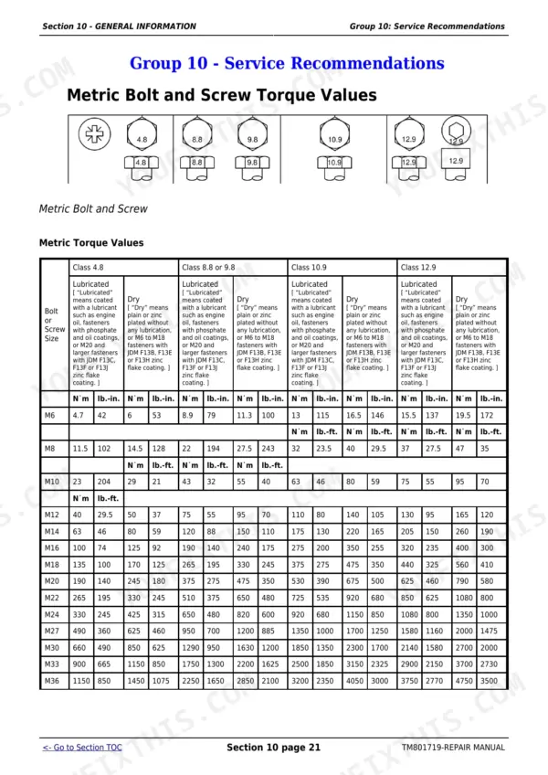
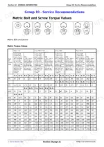
| Metric Bolt Torque (M10, Class 12.9, Lubricated) | 75 N.m (55 lb-ft) | p. 37 |
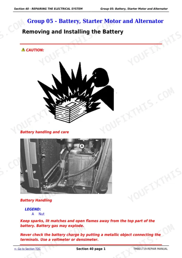
| Battery Nut Torque | 5 N·m | p. 43 |
| Clutch Pedal Play | 25 - 30 mm (0.984 - 1.181 In) | p. 87 |
| PTO Clutch Disc Thickness | 7.6–6.6 mm | p. 88 |
| Engine to Clutch Housing Bolt Torque | 275 N.m (193 lbf-ft) | p. 81 |
| ROPS Mounting Bolts Torque | 335 N.m (247 lb-ft) | p. 400 |
John Deere 5055E-5090E Common Problems This Manual Covers
PTO driveline makes grinding or rattling noise during operation, vibration felt through shaft
Inspect the PTO lever, link, and drive shaft assembly per the procedure beginning on page 216. Check shaft splines for galling and measure PTO clutch disk thickness; replace any disk worn below 6.6 mm (page 92). Verify all drive shaft fasteners are tight before running under load. If noise persists, disassemble and inspect universal joints.
Manual Section: Group 20 - PTO Drive Shaft p. 216Coolant temperature warning triggers repeatedly at normal operating temps, no actual overheating
Remove the coolant temperature sensor and inspect threads and sealing surface for corrosion or damage. Apply LOCTITE 243 (L41475) to the threads before reinstalling (page 48). Verify the sensor connector and wiring harness for damage using the electrical system diagram on page 66. If readings stay erratic after sensor replacement, trace the circuit from page 42.
Manual Section: Repairing the Electrical System p. 48Frequently Asked Questions
What are the torque specifications for wheel bolts on John Deere 5075E?
The wheel bolts for the John Deere 5075E should be tightened to a torque of 175 N.m (130 lbf-ft). This specification applies when installing fenders and wheels, as detailed in the TSS Transmission and PTO Drive Shaft sections. p. 129
How do you fix john Deere 5055E engine cranks slowly or won't fire, dashboard warning lights stay dim?
Check battery terminals for corrosion, then torque both nuts to 5 N·m per the procedure on page 43. Inspect the starter motor and alternator following service procedures beginning on page 42. Test battery voltage under load before condemning the starter; a weak cell often mimics a failed starter or ignition fault on these tractors. p. 42
How do you fix hydraulic lift drops slowly after engine shutdown, implements sag and won't hold position?
Remove and inspect the hydraulic pump using procedures beginning on page 328. Pull the mesh filter, clean it, and torque the cover bolts to 23 N·m after reinstalling (page 345). Check hitch control and relief valves in the Hydraulic Hitch and SCV Repair section. If hitch attaching nuts were disturbed, torque them to 400 N·m (page 375). p. 328
How do you fix clutch slips under load, pedal travel is excessive, gears grind or refuse to engage?
Measure clutch pedal free play; on 5075E, 5078E, 5085E, and 5090E, spec is 25-30 mm (0.984-1.181 in) per page 87. Remove the LUK clutch assembly per page 88 and measure PTO clutch disk thickness. Replace any disk worn below 6.6 mm (page 92). Torque clutch assembly attaching bolts to 36 N·m on reinstall (page 93). p. 88
How will I receive this John Deere 5055E & variants Repair Manual?
A 402-page Repair Manual in searchable PDF format, available the moment you complete checkout. View on computer, tablet, or phone, with no shipping wait.
Am I able to print pages from this manual?
Yes. Print individual pages or full chapters for your own shop use, on letter or A4 paper.









Reviews
There are no reviews yet.