
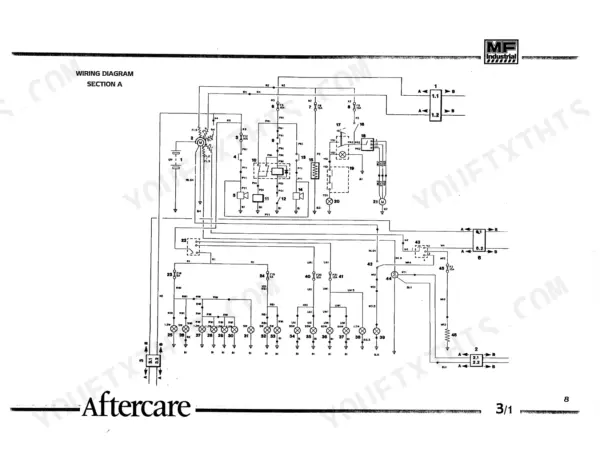
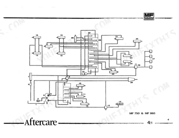
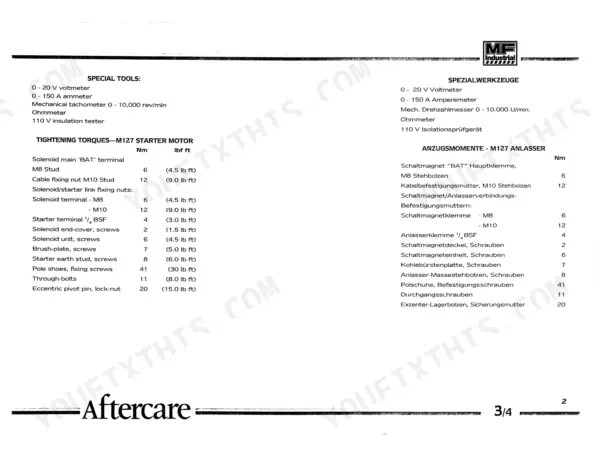
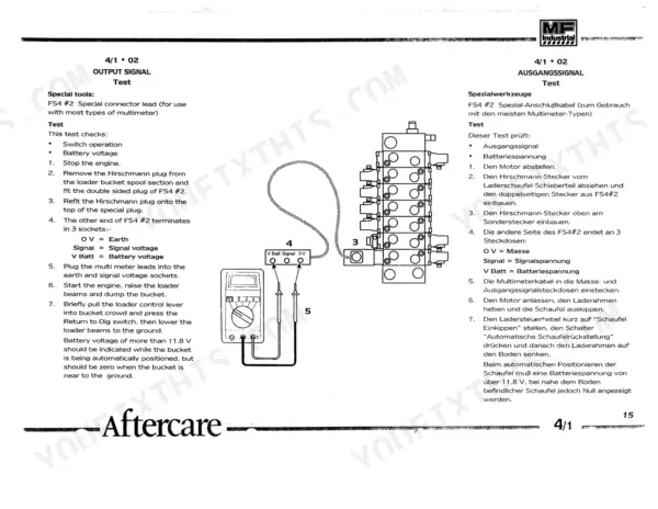
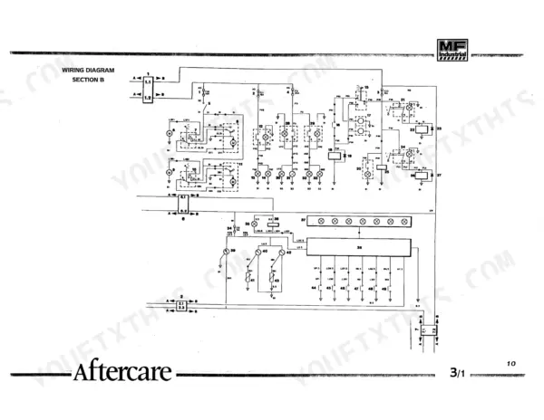
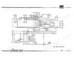
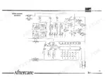
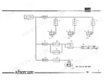
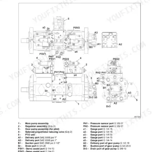
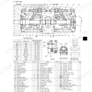
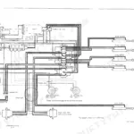
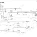
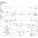
A Kobelco TLK series loader backhoe can be stripped to the axles and rebuilt using the 620 pages in factory publication 3517-457-M1-00 NA, which covers four models. The electrical system takes up a large share of this Kobelco TLK 750, 860, 865, 965 service manual PDF, with wiring diagrams that trace your battery, charging and starting circuits. Hydraulic schematics show oil routing through the main control valve, Dukes valve and auxiliary valve. The transmission chapter, one of the longest in the book, works through the powershuttle, 4WD pod, 4 wheel steer pod and 5th speed clutch. Set fan belt deflection to 13 to 19 mm midway between the fan and crankshaft pulleys, and torque the starter solenoid end-cover screws to 2 Nm (1.5 lb ft). A made-up torque on those screws strips the threads. The text is searchable and bookmarked, and the pages print clean, so you can take the brake chapter to the bench and let it soak up oil.
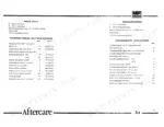
What's Inside This Kobelco TLK 750, TLK 860, TLK 865, TLK 965 Manual
| System | Pages | Key Topics |
|---|---|---|
| General Information | 6-15 | Safety Precautions, Using the Service Manual |
| Specifications | 16-37 | General Dimensions, Machine Specifications |
| Electrical System | 38-115 | Battery, Charging System, Starting System |
| Electro-Hydraulic System | 116-197 | Hydraulic System Mechanical Valves |
| Hydraulic Valves | 198-249 | Main Control Valve, Dukes Valve, Auxiliary Valve |
| Hydraulic Pumps | 250-265 | Hydraulic Pumps Service |
| Hydraulic Cylinders | 266-291 | Hydraulic Cylinders Service, Extending Dipperstick Cylinder |
| Power Steering | 292-321 | Power Steering System, Power Steering Cylinders |
| Brake System | 322-343 | Brake Control - 750/860/865, Brake Control - 965 |
| Major Assemblies | 344-367 | Major Assemblies Remove and Refit, Rear Axle Remove and Refit |
| Engine | 368-389 | Engine Service |
| Transmission | 390-465 | Powershuttle Transmission, 4WD Pod, 4WS Pod, 5th Speed Clutch |
| Rigid Drive Axle | 466-499 | Rigid Drive Axle Service |
| Steering Drive Axles | 500-561 | Drive-Steer Axle, 4 Wheel Steer Axles |
| Loader Structure | 562-571 | Loader Structure Service |
| Backhoe Structure | 572-587 | Backhoe Structure Service |
| Cab / ROPS / Chassis | 588-597 | Cab / ROPS Service |
| Attachments | 598-607 | Extending Dipperstick |
| Wheels and Tyres | 608-620 | Wheels and Tyres Service |
Quick Reference Specifications
| Specification | Value | Page |
|---|---|---|
| Fan belt tension | 13-19 mm | p. 22 |
| Hydraulic system filter rating | 13 micron absolute | p. 24 |
| Engine valve clearance (Exhaust) | 0.45 mm (0.018 in), hot or cold | p. 22 |
| Solenoid main 'BAT' terminal torque | 6 Nm (4.5 lb ft) | p. 102 |
| M8 Stud torque | 6 Nm (4.5 lb ft) | p. 102 |
| Hydraulic pump flow rate | 49 litres/min. at 225 bar | p. 123 |
| Fuel tank capacity | 98.0 L | p. 31 |
| Engine sump including filter capacity | 10.7 L | p. 21 |
| Hydraulic reservoir capacity | 45.0 L | p. 21 |
| Wheel nut tightness (Rear wheels) | 300 Nm | p. 26 |
| Wheel nut tightness (Front wheels) | 300 Nm | p. 26 |
| Engine valve clearance (Inlet) | 0.2 mm | p. 22 |
Kobelco TLK 750, TLK 860, TLK 865, TLK 965 Common Problems This Manual Covers
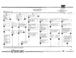
Kobelco TLK 750 860 865 965 electro-hydraulic loader return to dig ineffective and bucket self-level not working
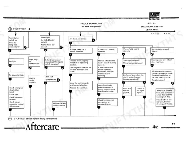
Run the electronic system quick test first, following the fault diagnosis section before touching any valve. Work through the return to dig and loader bucket self-level symptom checks in order. Check pump output against 49 litres/min. at 225 bar per page 123 so you know the hydraulics are healthy before chasing electrics.
Manual Section: Electro-Hydraulic System Fault DiagnosisMechanical valve machine loader bucket self-level malfunction with return to dig ineffective
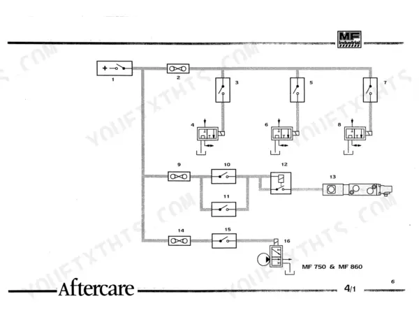
Verify the machine runs mechanical valves and not the electro-hydraulic system before you start, because the fault diagnosis is split between the two. Work through the return to dig and loader bucket self-level checks in order. Clear the general symptoms list in the same section before you strip any valve on the bench.
Manual Section: Hydraulic System Mechanical Valves Fault DiagnosisPowershuttle transmission no drive or drive in one direction only, with gears difficult to select
Check whether the fault is no drive at all, drive in one direction only, or slow drive engagement, then follow the matching Powershuttle fault diagnosis chart. Inspect for transmission overheating at the same time, since it sits in the same diagnosis table. Rule these out before stripping the Powershuttle transmission, covered from page 390.
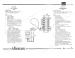
Manual Section: Powershuttle Transmission Fault DiagnosisStarting system solenoid not operating with battery voltage dropping under load when cranking
Test battery voltage under load first, then measure voltage drop across each cable and check continuity through the circuit to the solenoid. Verify solenoid operation before condemning the starter motor. When refitting, torque the solenoid end-cover screws to 2 Nm (1.5 lb ft) and the through-bolts to 11 Nm per page 102.
Manual Section: Starting System Diagnosis p. 102Battery failing open circuit voltage and load test with quiescent current drain suspected
Measure open circuit voltage with the machine switched off, then check quiescent current drain before you blame the battery. Run the battery load test next. Test charging system voltage with the engine running so you know whether the battery or the alternator is the real fault before you order parts.
Manual Section: Battery Fault DiagnosisCharging system battery indicator light abnormal with low alternator output or overcharging
Check battery indicator light status first and note exactly when it lights, then measure alternator output with the engine running. Verify whether you have an undercharge or an overcharging fault before replacing parts, and confirm battery condition with the battery fault diagnosis checks so a weak battery does not mislead the alternator test.
Manual Section: Charging System DiagnosisFrequently Asked Questions
What is the torque specification for the wheel nuts on the Kobelco TLK 750/860/865/965?
The wheel nuts for the Kobelco TLK 750/860/865/965 must be tightened to a torque of 300 Nm (220 lbf ft). p. 26
What is the correct valve clearance for the engine on the Kobelco TLK 750/860/865/965?
For all engines, the valve clearance is 0.2 mm (0.008 inches) for the inlet valve and 0.45 mm (0.018 inches) for the exhaust valve, measured hot or cold. p. 22
What is the fan belt tension specification for the engine on Kobelco TLK loader backhoes?
The fan belt tension should be 13-19 mm (1/2 inch - 3/4 inch), measured midway between the fan pulley and the crankshaft pulley. p. 22
What is the procedure for bleeding the brake system on the MF 965?
To bleed the brake system on the MF 965, rotate the wheels until the vent plug is at the top, clean the area, attach a plastic tube to the vent screw, and open the screw 1/2 turn while an assistant presses the brake pedal. Repeat until fluid emerges free of air bubbles, then close the screw. Repeat this for the rear right, front left, and front right brakes. p. 138
What is the connecting rod nut torque on the Kobelco TLK 750/860/865/965 engine?
Connecting rod nuts are torqued to 125 Nm (92 lbf ft) on both engine versions (MF 750 and MF 860/865/965 specifications). The cylinder head screw torque is not listed here; the manual refers you to the engine workshop manual. p. 374
How quickly can I access this Kobelco TLK 750 manual after buying?
This is a 620-page searchable PDF ready for immediate download. Works on any device, so pull it up on your phone while you're under the hood. No shipping, no waiting.
Can I print just the pages I need from this Kobelco TLK 750 manual?
Yes. Print the pages or sections you need for your own shop use. Any standard printer works.

Reviews
There are no reviews yet.