
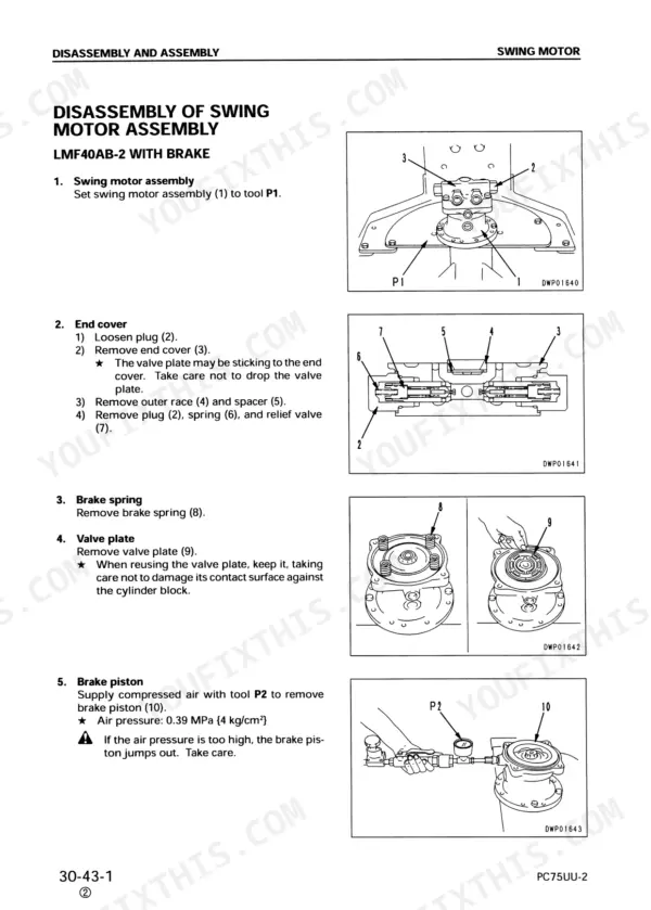
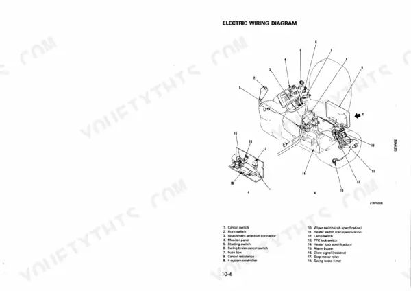
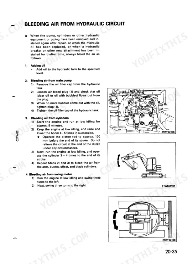
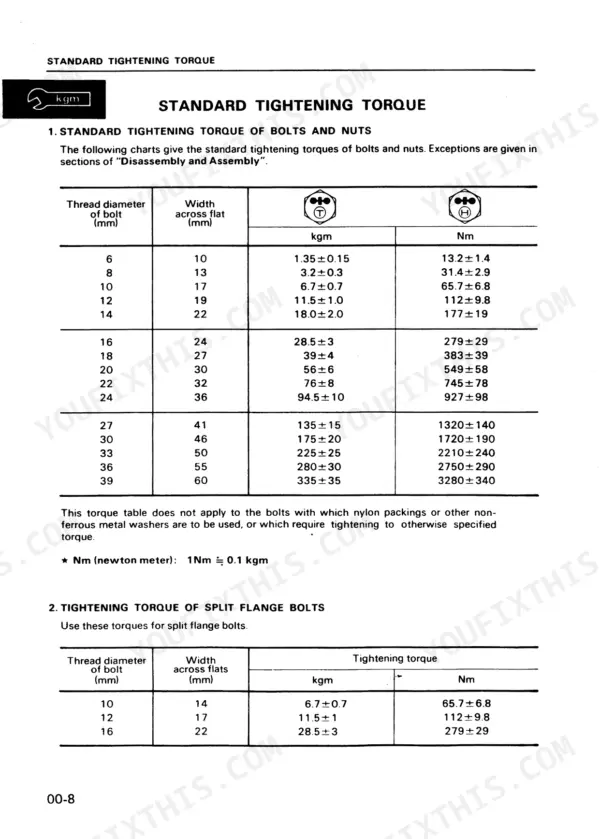
Need factory data for your Komatsu PC75UU-2? This 399-page Komatsu PC75UU-2 Service Manual PDF (OEM #SEBM001302) is the complete factory shop manual for the crawler excavator, running from structure and function through disassembly, assembly, and maintenance standards. Inside: electric wiring diagrams, hydraulic circuit and piping schematics, a full testing and adjusting section with judgement standard value tables, and page after page of teardown procedures for the swing machinery, track frame, and undercarriage. You get exact numbers, not estimates. Torque standard 8mm bolts to 3.2±0.3 kgm and 12mm bolts to 11.5±1.0 kgm before you button anything up. No more chasing wiring faults with a multimeter and a prayer. Bookmarked for quick jumps; pull it up on a phone or tablet next to the machine and get wrenching.
What's Inside This Komatsu PC75UU-2 Manual
| System | Pages | Key Topics |
|---|---|---|
| Safety | 5-6 | General Precautions, Preparations for Work, Precautions During Work |
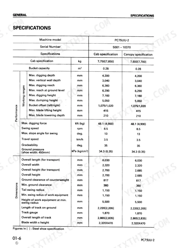
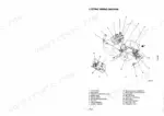
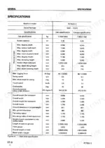
| General | 19-32 | General Assembly Drawing, Specifications, Weight Table, List of Lubricant and Water |
| Structure and Function | 33-39 | Hydraulic Piping Diagram, Hydraulic Circuit Diagram, Electric Wiring Diagram, Electric Circuit Diagram |
| Testing and Adjusting - Standard Values and Procedures | 40-93 | Standard Value Tables, Engine Speed Measurement, Compression Pressure, Valve Clearance Adjustment, Fuel Injection Timing, Track Shoe Tension, Hydraulic Pressure Testing, Potentiometer Reset Procedure |
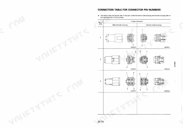
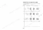
| Troubleshooting - Electrical System and Circuit Diagrams | 94-168 | Electrical Circuit Diagrams, Connector Pin Arrangement, Monitor Panel Self-Diagnostics, Controller Judgement Tables, Error Code Troubleshooting, Cancel Switch Handling |
| Troubleshooting - Hydraulic and Machine Monitor Systems | 169-206 | Hydraulic Fault Diagnosis, Failure Mode Table, Machine Monitor Troubleshooting, Swing Drift Diagnosis, Track Deviation Diagnosis, Fuel Gauge Faults |
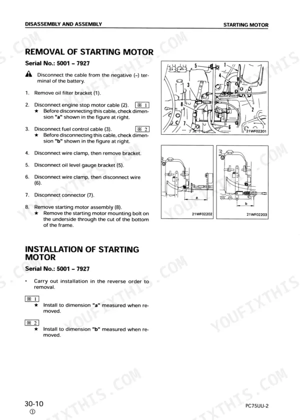
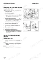
| Disassembly and Assembly - Special Tools and Engine Components | 207-241 | Special Tools List, Schematic Drawing of Special Tool, Starting Motor, Alternator, Fuel Injection Pump, Water Pump, Nozzle Holder, Cylinder Head |
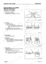
| Disassembly and Assembly - Cooling, Main Pump and Swing Components | 242-283 | Hydraulic Oil Cooler, Radiator, Engine and Main Pump, Center Swivel Joint, Travel Motor, Sprocket, Swing Motor, Swing Machinery |
| Disassembly and Assembly - Undercarriage and Main Pump | 284-333 | Idler and Recoil Spring, Track Roller, Carrier Roller, Rubber Shoe, Main Pump, 3-Spool Control Valve, 4-Spool Control Valve, Main Relief Valve |
| Disassembly and Assembly - Ppc Valve and Work Equipment Cylinders | 334-376 | Work Equipment Ppc Valve, Arm Cylinder, Bucket Cylinder, Boom Cylinder, Offset Cylinder, Blade Cylinder, Fuel Tank, Counterweight |
| Maintenance Standard | 377-399 | Swing Machinery, Swing Circle, Track Frame, Recoil Spring, Idler, Track Roller, Carrier Roller, Sprocket |
Quick Reference Specifications
| Specification | Value | Page |
|---|---|---|
| specified tightening torques | specified tightening torques | p. 6 |
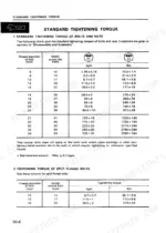
| Standard tightening torque of bolts and nuts (6mm) | 1.35±0.15 kgm | p. 10 |
| Standard tightening torque of bolts and nuts (8mm) | 3.2±0.3 kgm | p. 10 |
| Sealant gasket (LG-4) thickness after tightening | 0.07 - 0.08 mm | p. 11 |
| Revolving frame (without counterweight) | 1,980 kg | p. 28 |
| Hydraulic system capacity | 100 l | p. 30 |
| Delivery valve holder | 32.3 ± 1.9 Nm (3.3 ± 0.25 kgm) | p. 59 |
| Sleeve nut | 23.5 ± 0.9 Nm (2.4 ± 0.1 kgm) | p. 59 |
| Hydraulic tank | Approx. 75 l | p. 304 |
| Clearance between gear and side plate (Standard clearance) | 0.10 – 0.15 mm | p. 387 |
| Clearance between inside diameter of plain bearing and outside diameter of gear shaft (Standard clearance) | 0.060 – 0.119 mm | p. 387 |
| Pilot poppet spring of main relief valve (Standard size - Free length x OD) | 30.65 × 9.6 | p. 389 |
Komatsu PC75UU-2 Common Problems This Manual Covers
Komatsu PC75UU-2 hydraulic pump loses pressure after warm-up, boom and bucket cycle slow and weak
Test pump delivery pressure with oil at 45 to 55 degrees C; spec is 20.6 MPa (210 kg/cm2) at 3,500 rpm per page 387. If low, pull the pump and measure gear to side plate clearance; standard is 0.10 to 0.15 mm. Replace the pilot poppet spring if installed load falls below 243.2 N, the repair limit on page 391.
Manual Section: Maintenance Standard p. 387Coolant temperature gauge climbs into the red during continuous digging, monitor shows E01 code
Check the fan belt and radiator fins first. Drain the cooling system, which holds 9 L per page 30, flush the radiator, and refill with fresh coolant. Back-flush the hydraulic oil cooler too; a plugged cooler dumps heat into the radiator. Confirm the E01 code against the error code reference before condemning parts.
Manual Section: Testing and AdjustingMonitor display flickers or goes blank, intermittent error codes clear themselves after every restart
Verify battery voltage at the monitor connector before replacing the unit; trace the harness against the wiring diagram on page 38 and clean every ground point. Remove and reseat the monitor connectors, then torque the mounting nuts to 8.3 Nm (0.85 kgm) per page 374. Loose grounds and corroded pins cause most phantom codes on this machine.
Manual Section: Machine Monitor System Troubleshooting (M Mode)Track chains slip, stretch, or break early, sprocket teeth show hooked uneven wear
Inspect sprocket teeth and roller treads against the clearance specifications on page 399; hooked teeth mean the chain has stretched past its service limit. Check track shoe tension before blaming parts, since an over-tight chain kills bushings fast. When swapping shoes, rig a lifting device: each steel 450 mm shoe assembly weighs 447 kg per page 28.
Manual Section: Maintenance Standard p. 399Engine runs rough and hunts at low idle, white smoke on cold starts
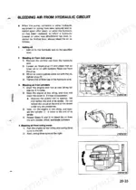
Check fuel injection timing following the engine diagnostics procedure, then crack each injector line at idle to find the dead cylinder. Bleed air from the fuel system after any line work. Torque delivery valve holders to 32.3 Nm (3.3 kgm) and sleeve nuts to 23.5 Nm (2.4 kgm) per page 59; over-tightening seizes the plungers.
Manual Section: Engine Diagnostics and Adjustment p. 59Frequently Asked Questions
How do I reset the KOMATSU PC75UU-2 electrical system after an error code appears?
The reset procedure (p.79-81) starts with resetting the potentiometer input signal: set the work equipment posture to boom at end of RAISE stroke, arm at end of IN stroke, and offset at end of right offset stroke; cycle the starting switch OFF then ON; then connect reset power source terminal (1, red female connector) to input reset terminal (2, red male connector) - these are taped to the wiring harness at the rear of the panel (3 terminals on serial No. 5001-5494, 4 terminals from 5495 up). The electrical system caution lamp should start flashing in 1-second cycles 2 seconds later; if no error code (11-1F) appears, disconnect the terminals and turn the switch OFF to complete the reset. p. 79
What are the torque specifications for KOMATSU PC75UU-2 engine bolts?
Specific torque specifications for engine bolts include the nozzle holder mounting nut at 44.1 ± 4.9 Nm {4.5 ± 0.5 kgm} and cylinder head bolts, which require a two-step tightening process: 1st time to 68.6 ± 9.8 Nm {7 ± 1 kgm} and 2nd time to 107.9 ± 4.9 Nm {11 ± 0.5 kgm}. p. 58
What are the error codes for the KOMATSU PC75UU-2?
The KOMATSU PC75UU-2 displays various error codes for abnormalities, including codes 21 (model selection system), 22 (work equipment selection system), 31 (boom potentiometer system), 41 (PPC lock solenoid system), and 61 (valve open system). A comprehensive list of error codes and their corresponding abnormal systems can be found in the troubleshooting section. p. 128
What is the standard tightening torque for bolts and nuts on the KOMATSU PC75UU-2?
The general STANDARD TIGHTENING TORQUE table (p.10) scales by bolt thread diameter: M8 = 31.4 ± 2.9 Nm, M10 = 65.7 ± 6.8 Nm, M12 = 112 ± 9.8 Nm, M16 = 279 ± 29 Nm, M20 = 549 ± 58 Nm, and M24 = 927 ± 98 Nm. Components with a different required torque (e.g. the nozzle holder mounting nut at 44.1 ± 4.9 Nm, or cylinder head bolts up to 107.9 ± 4.9 Nm) are called out individually inside the Disassembly and Assembly and Testing and Adjusting sections rather than using this general table. p. 10
How quickly can I access this Komatsu PC75UU-2 manual after buying?
Instant PDF download. You get the full 399-page searchable Service Manual immediately after payment. Open it on your laptop, tablet, or phone right in the shop.
Can I print specific sections of this Komatsu PC75UU-2 Service Manual?
No restrictions at all. Print individual pages, full chapters, or the entire manual. The PDF is completely unlocked.



Reviews
There are no reviews yet.