| Operation and Controls | 5-6 | Throttle Lever, Engine Stop Position, Low Idle Setting, Travel Control Lever, Pilot Valve Lever Stroke, Secondary Pressure |
| Specification | 7-22 | Names of Components, General Dimensions, Specifications and Performance |
| Location and Weight of Components | 23-28 | Location of Components, Weight of Components, Transportation Weight |
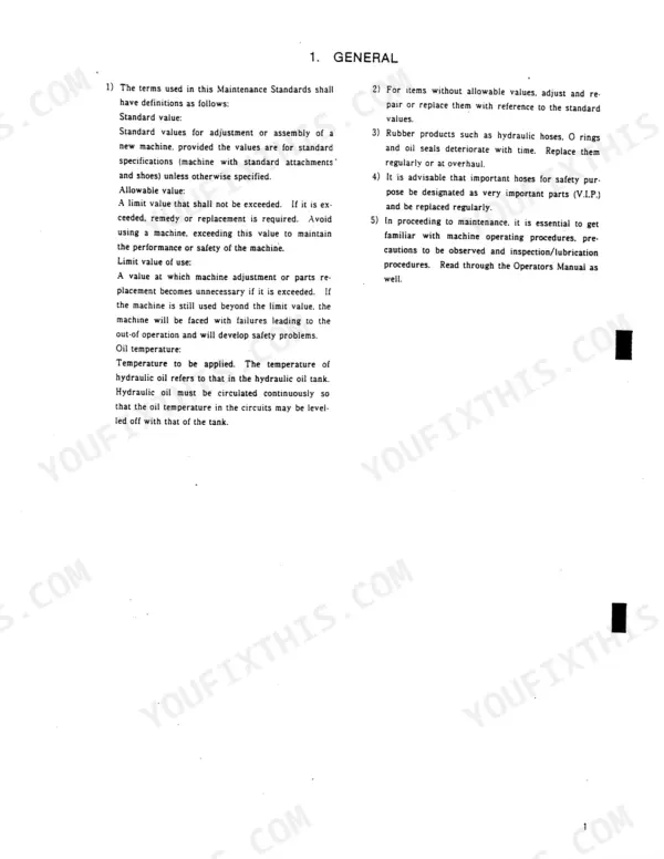
| Maintenance Standards and Test Procedures | 29-44 | Pressure Measurement and Adjustment, Cylinder Speed, Cylinder Oil-Tightness, Swing Performance, Travel Performance |
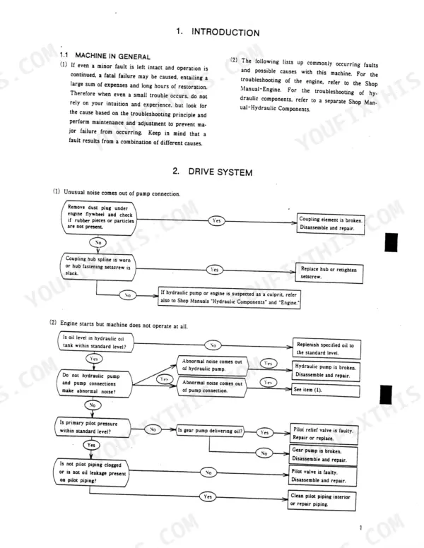
| Troubleshooting | 45-69 | Drive System, Hydraulic System, Swing System, Travel System, Attachment System, Electrical System |
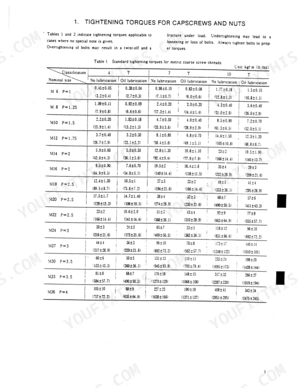
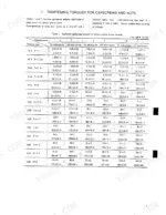
| Tightening Torques for Capscrews and Nuts | 70-73 | Metric Coarse Screw Threads, Metric Fine Screw Threads, Nuts and Sleeves Tightening Torques |
| Systems Section Overview | 74-75 | Drive System, Hydraulic System, Swing System, Travel System, Attachments, Control System, Upper Frame, Electrical System |
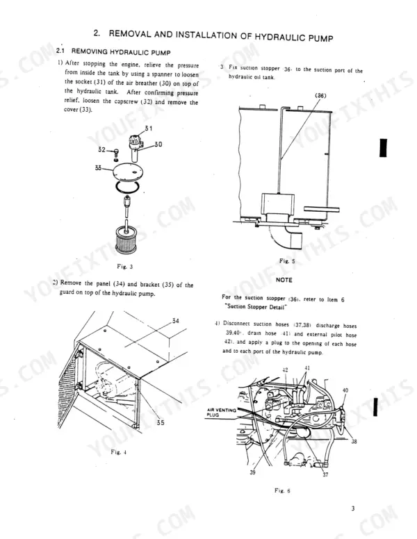
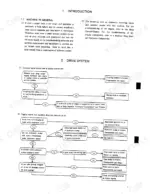
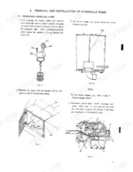
| Drive System | 76-87 | Power Plant, Hydraulic Pump Removal and Installation, Coupling Removal and Installation, Engine Removal and Installation, Suction Stopper Detail |
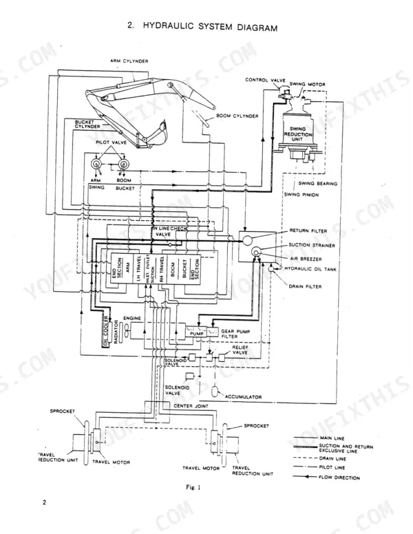
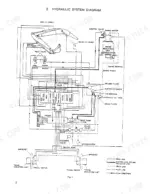
| Hydraulic System | 88-106 | Hydraulic System Diagram, Travel Circuit, Boom Circuit, Arm Circuit, Bucket Digging, Swing Circuit, Negative Control Signal Circuit |
| Swing System | 107-116 | Swing System Operation, Swing Bearing, Swing Grease Bath, Swing Control Valve, Swing Motor, Swing Reduction Unit |
| Travel System | 117-149 | Lower Machinery Construction, Travel System Function, Track Link, Upper Roller, Lower Roller, Idler and Track Spring, Travel Reduction Unit, Sprocket |
| Attachments | 150-166 | Attachment System Functions, Backhoe Attachments, Bucket Removal and Installation, Arm Removal and Installation, Boom Removal and Installation, Pin and Bushing Clearance |
| Control System and Electrical System | 167-179 | Engine Control System, Travel Control System, Hydraulic Control System |
| Upper Frame | 180-194 | Fuel Tank, Removal and Installation of Counterweight, Removal and Installation of Cab |
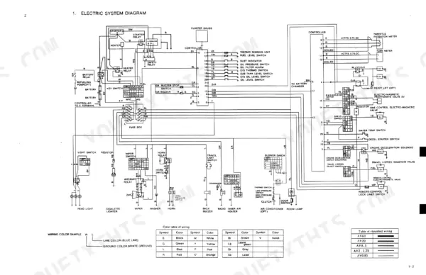
| Electric System Diagram | 195-212 | Electrical System Diagram |
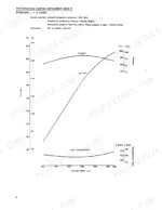
| Hydraulic Pump | 213-258 | Pump Control Curves, Pilot Valve |
| Control Valve | 259-330 | Main Relief Valve, Travel Relief Valve |
| Hydraulic Motor | 331-374 | Function of Brake Valve, Mounting Position of Changeover Valve |
| Swivel Joint | 375-388 | Thrust Plate, Slipper Ring, Square Ring |
| Hydraulic Cylinder | 389-408 | Tools and Jigs List |
| Reduction Unit | 409-441 | Planetary Shaft, Sun Gear, Pinion Shaft Assembly |
| Heavy Lift | 442-454 | Heavy Lift Modification |