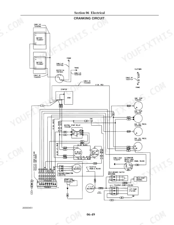
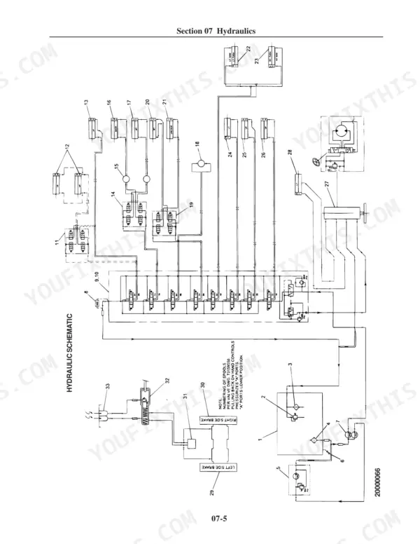
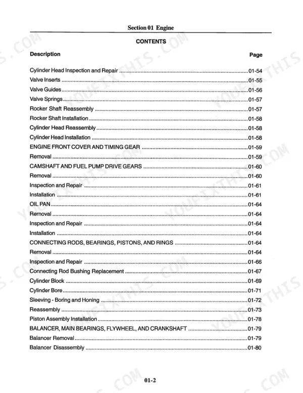
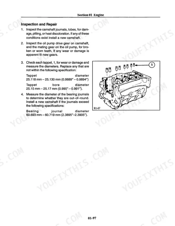
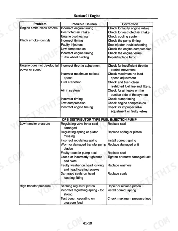
This 664-page New Holland Construction RG80, RG100 Service Manual (OEM #75131050) breaks down every system on your Road Grader, from the diesel engine and torque converter transmission to the hydraulics that run the moldboard. You get full wiring schematics for the cranking, charging, and warning light circuits, hydraulic schematics covering the pump and control valve, and page after page of exploded views for the front axle, tandem drives, and moldboard assembly. Troubleshooting charts walk you through starter and alternator faults step by step, and a dedicated torque section keeps every bolt where the factory wants it. Set starter cranking current between 325 and 375 amps, and confirm ground cable voltage drop stays under 0.2 volts before you chase a phantom no-start. No more swapping parts on a guess when your grader won't turn over. Bookmarked by section, so you can jump straight from the cover page to hydraulics without scrolling through 664 pages.
What's Inside This New Holland RG80, RG100 Manual
| System | Pages | Key Topics |
|---|
| Engine | 12-193 | Description of Operation, Cylinder Head Assembly, Camshaft Assembly, Crankshaft Assembly, Connecting Rods, Pistons, Manifolds |
| Transmission | 194-255 | General, Torque Converter, Hydraulics, Control Valve Unit Solenoid Selection Code, Transmission Schematic, Electrical, Specifications, Special Tools |
| Front Axle | 256-299 | Adjustments, Front Axle Toe-In, Steering Cylinder, Front Wheel Bearings, Disassembly and Repair, LH Steering Knuckle and King Pin Removal, RH Steering Knuckle and King Pin Removal |
| Rear Axle and Tandems | 300-375 | General, Specifications (Rear Axle, Differential, Drive Shaft, Tandem Box), Troubleshooting, Rear Axle and Tandem Drive Assembly (Removal) |
| Electrical | 376-444 | General, Definitions of Electrical Terms, Starting and Charging, Specifications, Special Tools, Troubleshooting (Preliminary Troubleshooting, Chart) |
| Hydraulics | 445-556 | Hydraulic Schematic, General, Specifications, Special Tools, Troubleshooting, Pressure Settings (Main Relief Valve, Fan Motor), Adjustments (Control Lever Linkage) |
| Operator’s Platform and Controls | 557-629 | Section Index - Operator’s Platform |
| Moldboard and Implement | 630-664 | Special Tools, Disassembly and Repair, Drawbar, Drawbar Removal, Drawbar Installation, Circle, Circle Removal, Circle Installation |
Quick Reference Specifications
| Specification | Value | Page |
|---|
| All Models |
| Maximum acceptable voltage drop between starter solenoid and positive battery post or between ground stud and engine ground | 0.2 volts | p. 387 |
| Starting Motor Rating | 3.1 Kw (4.2 Horsepower) | p. 380 |
| Starting Motor Cranking Ratio | 12.8:1 (128T Flywheel; 10T Starter Pinion) | p. 380 |
| Jumper wires | Special Tool (no specific clearance, torque, or replacement values provided) | p. 382 |
| Maximum acceptable voltage drop for Battery Ground Cable | 0.2 volts | p. 392 |
| Control Valve Unit Socket Head Mounting Screws Torque | 20 Nm (14.7 lb-ft) | p. 209 |
| Controller Replacement | replace controller | p. 212 |
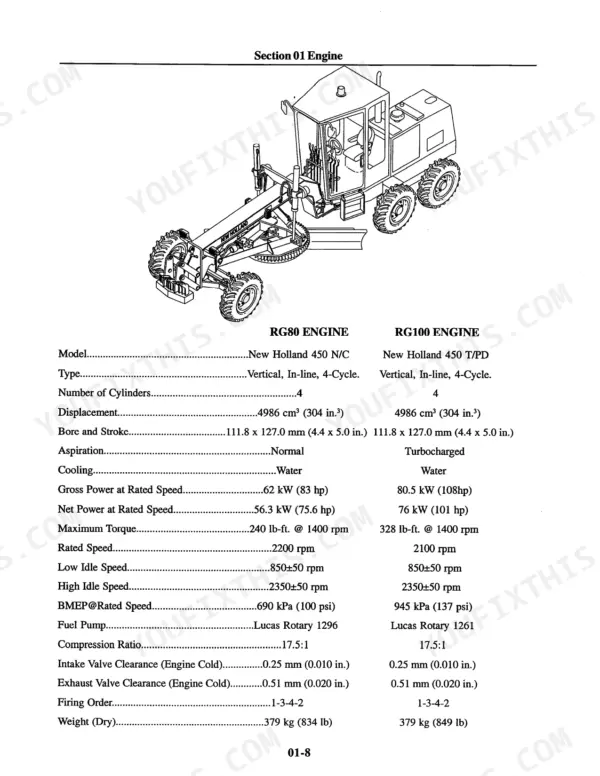
| Engine Cylinders | 4 | p. 4 |
| Engine Displacement | 5.0L (304 cu.in.) | p. 19 |
| Transmission Clutch Main Pressure | 16 – 18 bar (232 – 261 psi) @ 2000 rpm | p. 201 |
| RG80 |
| RG80 Rated Horsepower | 75.6 | p. 19 |
| RG100 |
| RG100 Rated Horsepower | 101 | p. 19 |