
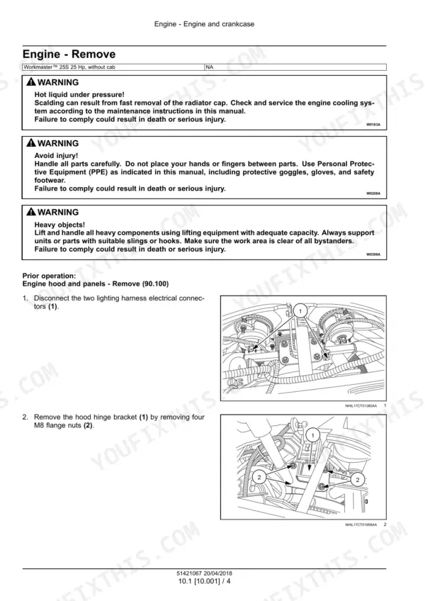

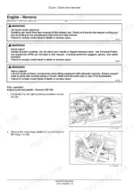
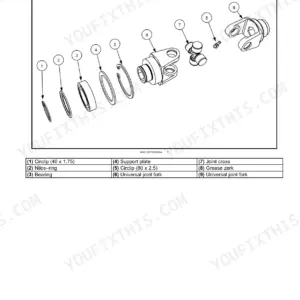
Built for one machine only, the Workmaster 25S compact tractor, this 925-page New Holland Workmaster 25S service manual PDF carries OEM ID 51421067 and follows the factory print page for page. Wiring diagrams take up nearly a third of the book, tracing every harness and connector on your tractor, from the cold start aid through cruise control and the parking brake circuit. Hydraulic schematics map oil from the fixed displacement pump through the relief valves to the three-point hitch control valve, and the hydrostatic transmission gets a complete teardown and rebuild sequence. Set belt deflection at 10 to 14 mm, and torque wheel discs, front and rear, to 43 to 57 N·m. Guess at a hydraulic port torque and threads strip. Bookmarked, text-searchable, and clean off a printer, this PDF lets the pages you need ride to the bench, take grease, and still read fine when your weather window opens.
Complete the set for your Workmaster 25S
- Operator Manual: New Holland Workmaster 25S Operator Manual
What's Inside This New Holland Workmaster 25S Manual
| System | Pages | Key Topics |
|---|---|---|
| Introduction | 6-31 | Foreword - Important Notice Regarding Equipment Servicing, Safety Rules, Safety Rules - Ecology and the Environment, Torque - Standard Torque Data for Hydraulic Connections |
| Engine | 32-113 | Engine and Crankcase, Fuel Tanks, Fuel Filters, Air Cleaners and Lines, Intake and Exhaust Manifolds, Engine Cooling System, Fan and Drive |
| Four-Wheel Drive (4WD) System | 114-121 | Drive Shaft |
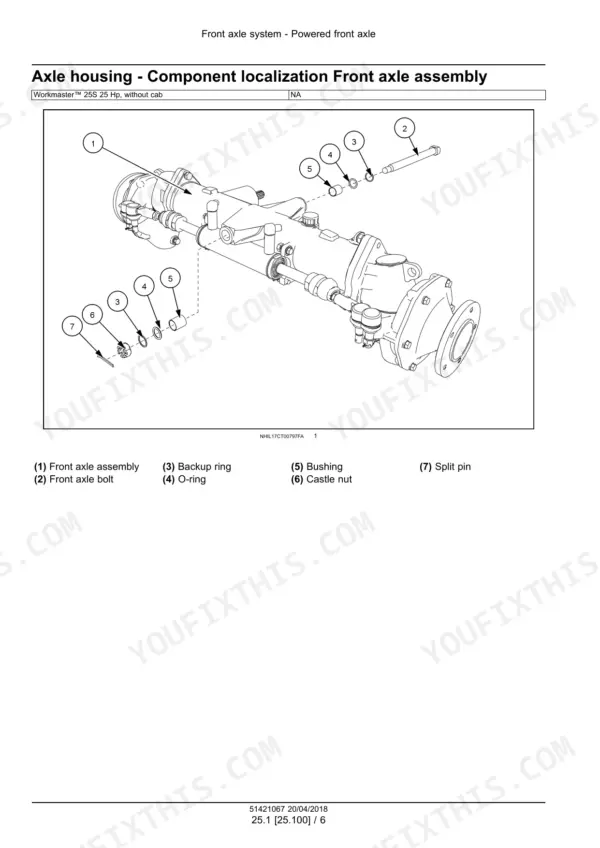
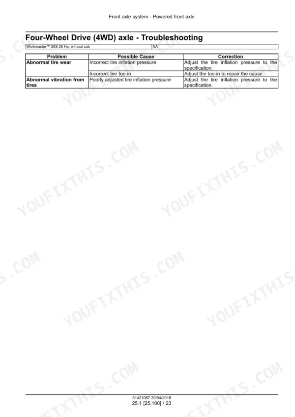
| Front Axle System | 122-183 | Powered Front Axle, Front Bevel Gear Set, Final Drive Hub |
| Rear Axle System | 184-219 | Powered Rear Axle, Rear Bevel Gear Set, Planetary and Final Drives |
| Hydrostatic Drive | 220-351 | Mechanical Control, Pump and Motor Components, Hydrostatic Transmission |
| Power Take-Off (PTO) | 352-381 | Rear Mechanical Control, Rear Electro-Hydraulic Control, One-Speed Rear PTO |
| Brakes and Controls | 382-415 | Mechanical Service Brakes, Parking Brake |
| Hydraulic Systems | 416-511 | Hydraulic Systems Overview, Reservoir, Cooler, And Filters, Fixed Displacement Pump, Safety and Main Relief Valves, Three-Point Hitch Control Valve, Hydraulic Hand Control |
| Hitches, Drawbars, and Implement Couplings | 512-521 | Rear Three-Point Hitch Linkage |
| Steering | 522-575 | Steering Control, Tie Rods, Steering Pump, Steering Cylinders |
| Wheels | 576-589 | Front Wheels, Rear Wheels |
| Electrical Systems | 590-899 | Electrical System, Harnesses and Connectors, Engine Starting System, Alternator, Battery, Cold Start Aid, Fuel Tank System, Fuel Injection System |
| Platform, Cab, Bodywork, and Decals | 900-925 | Operator Protections, Mechanically-Adjusted Operator Seat, Engine Hood and Panels |
Quick Reference Specifications
| Specification | Value | Page |
|---|---|---|
| Torque values for metric O-Ring Boss (ORB) port connections | 10.5 N·m (7.7 lb ft) to 525 N·m (387.2 lb ft) | p. 12 |
| Torque values for metric O-Ring Boss (ORB) port plugs | 8.5 N·m (6.3 lb ft) to 525 N·m (387.2 lb ft) | p. 12 |
| Front wheel disc-to-hub torque | 43 – 57 N·m (32 – 42 lb ft) | p. 23 |
| Rear wheel disc-to-axle torque | 43 – 57 N·m (32 – 42 lb ft) | p. 23 |
| Belt deflection | 10 – 14 mm (0.39 – 0.55 in) | p. 20 |
| Belt tension force | 98 N (22 lb) | p. 110 |
| Loader valve assembly M8 bolts torque | 28 N·m (21 lb ft) | p. 502 |
| Rated voltage | 12 V | p. 715 |
| Operating temperature range | 30 – 70 °C (86 – 158 °F) | p. 715 |
| Engine gross horsepower | 18.4 kW (24.7 Hp) @ 3000 RPM | p. 20 |
| Fuel tank capacity | 25 L (6.6 US gal) | p. 20 |
| Cooling system capacity | 3.3 L (3.49 US qt) | p. 20 |
New Holland Workmaster 25S Common Problems This Manual Covers
New Holland Workmaster 25S loses drive speed after normal operation, reverse goes weak or hydro pedal feels limp
Pull the right-hand floorboard and inspect the hydro pedal linkage for a sheared roll pin; replace the pin and reconnect the linkage. If the pedal is intact, verify HST charge pressure reads 101 to 130 psi using the procedure on page 339, and confirm transmission oil is at the full 12.5 L (3.3 US gal) capacity.
Manual Section: Hydrostatic Drive p. 220Engine runs hot or overheats under load, especially during mowing or heavy loader work
Clean the radiator screen and blow debris out of the fins with compressed air. Check coolant against the 3.3 L (3.49 US qt) system capacity. Test fan belt deflection; you want 10 to 14 mm (0.39 to 0.55 in) under 98 N (22 lb) of force, following the adjustment procedure on page 110.
Manual Section: Engine p. 110PTO will not engage or quits mid-job with the switch on and engine running
Check the PTO fuse and verify 12 V at the clutch solenoid connector with the switch engaged. Test the coil for continuity and replace it if open. If the electrical side checks out, tee in a gauge and confirm PTO relief valve pressure of 188 to 277 psi against the spec on page 371.
Manual Section: Power Take-Off (PTO) p. 371Three-point hitch will not lift the implement or settles as soon as engine slows
Check transmission oil level first; the hitch shares the 12.5 L (3.3 US gal) HST reservoir and a low level starves the pump. Inspect the suction filter for plugging. Then test main relief pressure at the lift circuit; it should hold 1885 to 1958 psi, the setting listed on page 22.
Manual Section: Hydraulic Systems p. 416Loader joystick gets sloppy or base plate works loose, control response feels vague
Remove the joystick boot and check the jam nut; torque it to 39 N·m (29 lb ft) per page 500. Inspect the base plate for cracks and retighten the loader valve assembly M8 bolts to 28 N·m (21 lb ft), the spec on page 502. Replace a cracked plate before it spreads.
Manual Section: Hydraulic Systems p. 500Frequently Asked Questions
What are the torque specifications for the hydraulic connections on the Workmaster 25S?
The torque specifications for hydraulic connections vary based on the thread size and type. For example, a metric O-Ring Boss (ORB) port connection with an M10x1 thread requires 21 N·m (15.5 lb ft) for ferrous materials and 12.5 N·m (9.2 lb ft) for non-ferrous materials. Always refer to the specific tables in the Introduction section for the exact connection type. p. 12
What is the engine oil capacity for the Workmaster 25S?
The engine crankcase capacity for the Workmaster 25S, including the filter, is 2.9 L (3 US qt). p. 20
What is the correct belt deflection for the engine cooling system fan drive?
The fan drive belt deflection should be 10 – 14 mm (0.39 – 0.55 in) when 10 kgf (22 lbf) of pressure is applied midway between the belt pulleys. p. 20
How do I bleed the fuel injection system on the Workmaster 25S?
To bleed the fuel system, ensure there is adequate fuel in the tank, then operate the hand primer lever on the left-hand side of the engine until air-free fuel flows into the fuel filter bowl. Continue for an additional 20 strokes, then start the engine and run it at 3/4 throttle until it operates smoothly. p. 73
What is the torque specification for the ROPS to rear axle bolts on a New Holland Workmaster 25S?
The attaching bolts for the Roll Over Protective Structure (ROPS) to the rear axle must be torqued to 76 N·m (56 lb ft). p. 23
What format is this New Holland Workmaster 25S manual in?
You get a 925-page searchable PDF that downloads instantly after checkout. Open it on your laptop, tablet, or phone, and bring it right to the shop floor.
Does this New Holland Workmaster 25S manual allow printing?
Printing is allowed without restriction. Pull the pages you need for the job and bin them when they get greasy.

Reviews
There are no reviews yet.