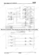
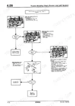
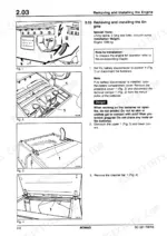
Factory documentation settles the technical questions that no aftermarket guide can answer, making this 458-page Bomag BC 601 RB, BC 601 RS repair manual PDF the primary resource for servicing your sanitary landfill compactor. Issued under OEM ID 008 191 44, the text lays out the full hydraulic diagram alongside detailed pressure testing protocols for the closed-loop travel pump. The electrical section maps out complete wiring diagrams and relay board testing charts to isolate faults quickly. Exact factory measurements verify your assembly work, including the 1100 Nm torque call on page 135. Guessing at made-up torque values or charge pressures is a fast way to destroy a hydrostatic drive in the middle of a cell. Download this bookmarked file to diagnose the fault accurately and keep the machine packing trash.
What's Inside This Bomag BC 601 RB, BC 601 RS Repair Manual
| System | Pages | Key Topics |
|---|
| General | 11-34 | Safety Regulations, Technical Data, Torques, Connecting Points, Special Tools |
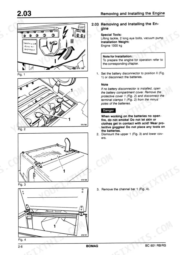
| Engine | 35-70 | Checking the Diesel Engine Speed, Checking the Peheating System, Removing and Installing the Engine, Preparing the Engine for Operation, Changing the Coupling |
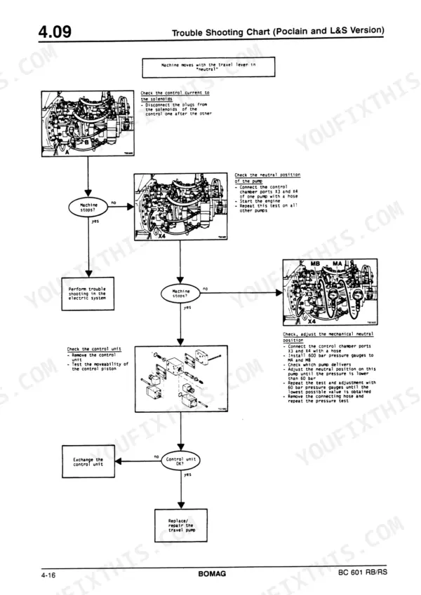
| Travel System | 71-178 | Pressure Tests in the Travel System, Checking High Pressure Relief Valves and the Pressure Cut-Of, Charge Pump High Pressure Test, Travel Pump High Pressure Test |
| Wheels | 179-184 | Welding the Shoe Segments, Changing the Wheel Tips |
| Steering/Dozer Blade Hydraulics | 185-262 | Checking the Setting of the Steering/Dozer Blade Pump, Checking the Pump High Pressure, Checking the Dozer Blade Precontrol Pressure |
| Electric System | 263-312 | Overall View of Installation Box, Most Important Circuits, Relay Board, Testing the Relay Board, Testing Chart for Relay Board, Relay Board for Brake Control |
| Electrical System From Machine No. and Up | 313-344 | Most Important Electric Circuits, Time-Invariant, Clutch for Air Conditioning System, Control of the Central Lubrication System, Monitoring Board, Testing the Monitoring Board |
| Circuit Diagrams | 345-384 | Hydraulic Diagram, Wiring Diagram Up to Machine-No., Wiring Diagram Since Machine-No. |
| Optional Equipment (Air Conditioning System) | 385-458 | Physical Basics, Refrigerant Circuit, Components, Technical Data, Safety Instructions for the Air Conditioning System, Notes for Repairs |
Quick Reference Specifications
| Specification | Value | Page |
|---|
| All Models |
| Grub screw tightening torque | 46 Nm | p. 50 |
| V-belt tension (thumb pressure depression) | 10 to 15 mm | p. 45 |
| Mounting screws (edge cutter) | 628 Nm | p. 135 |
| Installation Weight | approx. 10 kg | p. 249 |
| Rated power DIN 6271 IFN | 200 kW | p. 17 |
| High pressure relief setting | 450 bar | p. 18 |
| Fuel tank capacity | 500 L | p. 19 |
| Engine oil capacity | 23 L | p. 19 |
| Hydraulic oil capacity | 350 L | p. 19 |
| Refrigerant filling quantity | 2100 to 2200 g | p. 398 |
| BC 601 RB |
| Basic weight (L&S final drives) | 27493 kg | p. 17 |
| BC 601 RS |
| Basic weight (L&S final drives) | 27743 kg | p. 17 |