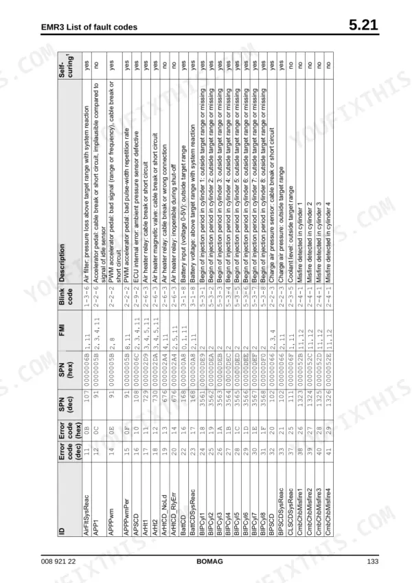
Covering the BF 600 C-HSE and C-HCE road finishers, this 778-page Bomag BF 600 C-HSE, BF 600 C-HCE service manual PDF (OEM 008 921 22) delivers the factory procedures needed to keep your paving train moving. Massive sections of this document break down the closed-loop travel pumps, vibration drives, and screed leveling systems with detailed hydraulic schematics and testing routines. Technicians can trace EMR3 system faults using extensive diagnostic code lists, while full-machine circuit diagrams clarify complex pulse-width modulation signals. You will find exact factory tolerances, like the left scraper chain pressure test port rated at 190 bar and the rail pressure sensor torque set to 40 + 5 Nm. When a cold mat threatens the shift because of a mystery sensor fault, lacking the right test value costs you time and density. Grab this searchable, bookmarked file to diagnose the issue accurately the first time and put your machine back in the pass.
What's Inside This Bomag BF 600 C-HSE, BF 600 C-HCE Manual
| System | Pages | Key Topics |
|---|
| General | 7-28 | Introduction, Safety Regulations, Tightening Torques |
| Technical Data | 29-38 | Weights, Travel Characteristics, Drive, Crawler Assembly, Hopper, Scraper Belt / Auger, Conveyor Auger, Screed |
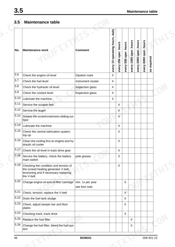
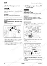
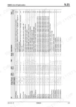
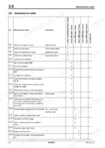
| Maintenance | 39-48 | Fuels and Lubricants, Table of Fuels and Lubricants, Running-In Instructions, Maintenance Table |
| Fundamental Electrics | 49-96 | Understanding Wiring Diagrams, Circuit Symbols in the Circuit Diagram, Battery Ground and Analog Ground, Processor Signals, Current and Voltage, Pulse Width Modulation, Resistance |
| Engine Electrics | 97-222 | Installation Location for Engine Control Unit, EMR3 System Components, Pin Assignment of Engine Control EDC16 / EMR3, Camshaft Speed Sensor, Crankshaft Speed Sensor |
| Engine | 223-278 | Diesel Engine, Engine Description Tcd 2013, 4 and 6 Cylinder, Lubrication Oil Circuit Tcd 2012 / 2013, Coolant Circuit Tcd 2012 / 2013, Fuel System Tcd 2012 / 2013 |
| Hydraulics | 279-360 | Hydraulic Circuit, Travel System, Actuator Drive, Scraper Chain Drive, Vibration and Tamper Drive, Fan Drive |
| Tests and Adjustments | 361-376 | Checking and Adjusting the Vibration, Checking and Adjusting the Tamping Process, Checking/Adjusting the Mobile Screed, Checking/Adjusting the Hopper Wings |
| Central Lubrication System | 377-400 | BF 600C with HC Screed (32-Point Lubrication), BF 600C with HC Screed (34-Point Lubrication), Filling the Lubricant Container, Electric Pump, Integrated Electronic Control |
| Suppliers Documentation | 401-704 | Travel Pump, Travel Motor, Conveyor Screws - Scraper Belt Motor, Travel Gear |
| Circuit Diagrams | 705-778 | Hydraulic Diagram 2542306, Wiring Diagram DE006010 |
Quick Reference Specifications
| Specification | Value | Page |
|---|
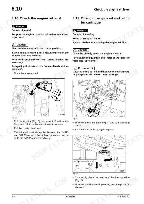
| Replace the hydraulic oil filter element | every 500 operating hours | p. 43 |
| Changing hydraulic oil and hydraulic oil filter | at least every 2 years | p. 47 |
| Tightening torque for crankshaft speed sensor | 9 Nm | p. 111 |
| Tightening torque for crankshaft speed sensor (gap adjustment) | 20 Nm | p. 113 |
| Pressure test port, scraper chain left | 190 bar | p. 330 |
| Pressure test port, scraper chain right | 190 bar | p. 330 |
| Fuel Tank Capacity | 215L | p. 31 |
| Engine Oil Capacity | 15L | p. 31 |
| Coolant Capacity | 20L | p. 31 |
| Hydraulic Oil Capacity | 160L | p. 31 |
| Engine Rated Power | 120 kW | p. 30 |
| Engine Rated Speed | 2300 min-1 | p. 30 |