From travel pump to Boss safety system, this 71-page Bomag BMP 8500 Service Training PDF walks the multi-purpose compactor's drive, vibration, hydraulic and electrical circuits end to end. The electrical section runs pages 37 to 57 and teaches how BOMAG builds its circuit diagrams: resolved representation, potential and relay cross references, terminal strip, plug and pin overviews, and the DIN component codes that stay the same on every BOMAG. The machine's own diagram sheets are not in this book; they ship with the separate wiring documentation, and this section is what makes them readable. Exciter unit coverage splits high and low amplitude operation, and the control valve block section identifies every port, relief valve and hydraulic line connection down to the jumper hoses. When you teach a new Boss transponder, verify the safety field reaches its full 1.20 m length, and load the machine knowing its 1595 kg CECE operating weight. One dropped safety field and the whole trench stands still. Buy it once and this bookmarked, text-searchable PDF stays yours for the life of the machine.
Complete the set for your BMP 8500
What's Inside This Bomag BMP 8500 Manual
| System | Pages | Key Topics |
|---|
| BMP 8500 Overview | 2-12 | Technical Data, Machine and Engine Identification, Filling Capacities, Component Overview |
| Travel System | 13-16 | Travel Motor Components, Travel Motors, Travel Pump, Travel Pump Operation |
| Vibration System | 17-22 | Vibration System Components, Vibration Motor, Exciter Unit, High Amplitude, Low Amplitude, Leak Oil Port, Vibration Control |
| Control Valve Block | 23-27 | Valve Identification, Pressure Relief Valves, Port Identification, Connection Identification |
| Hydraulic Line Connections | 28-35 | Hydraulic Line Connections to Control Valve Block, Return Flow Connections, Steering Cylinder Connections, Travel and Vibration Motor Connections, Jumper Hoses |
| Overview of Drum | 36 | Drum Components, Drive Components, Bearing Components |
| Electrical Overview | 37-57 | Reading Direction, Resolved Representation, Potential Cross References, Relay Cross References, List of Components, Overview of Terminal Strips |
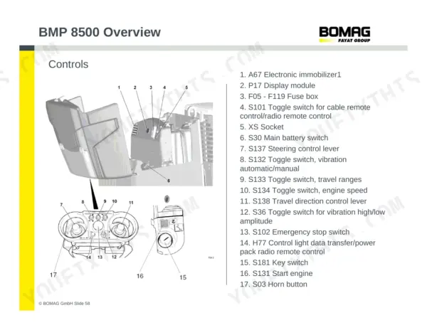
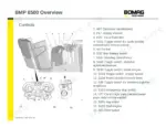
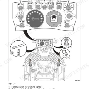
| Controls | 58 | Electronic Immobilizer, Display Module, Fuse Box, Remote Control Switches, Main Battery Switch, Steering Control Lever, Travel Direction Control Lever, Emergency Stop Switch |
| Fuses | 59 | Fuse Box Layout, Fuse Specifications, Fuse Functions |
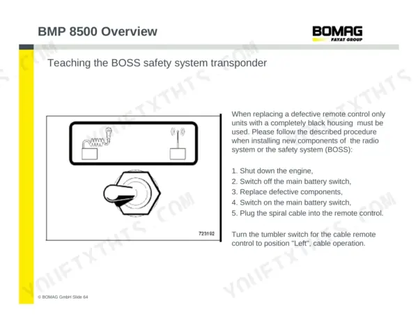
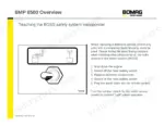
| Boss Safety System | 60-66 | Communication of Protection Field System, Teaching the Boss Safety System Transponder, Safety Field Measurement of the Boss Safety System |
| Fault Display Readout | 67 | Display Module, Flashing Fault Codes, Multiple Fault Indication |
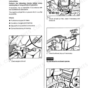
| Maintenance Procedures | 68-69 | Checking the Oil in the Vibrator Shaft Housing, Lifting the Machine, Opening Plugs, Checking Oil Level, Display Module Input Functions, Safety Bar Version, Safety Field Version |
Quick Reference Specifications
| Specification | Value | Page |
|---|
| Safety field length | 1.20 m/3.94 ft | p. 66 |
| Operating weight (CECE) | 1595 kg | p. 3 |
| Basic weight | 1585 kg | p. 3 |
| Mean axle load (CECE) | 775 kg | p. 3 |
| Engine rated power | 14.5 kW | p. 5 |
| Low idle speed | 850 rpm | p. 5 |
| High idle speed | 2750 rpm | p. 5 |
| Fuel tank capacity | 24 L | p. 10 |
| Hydraulic oil capacity | 17 L | p. 10 |
| Engine oil capacity | 4.7 L | p. 10 |
| Coolant capacity | 4.5 L | p. 10 |
| Travel pump high pressure limitation | 250 bar | p. 15 |
| Vibration system frequency | 42 Hz | p. 7 |