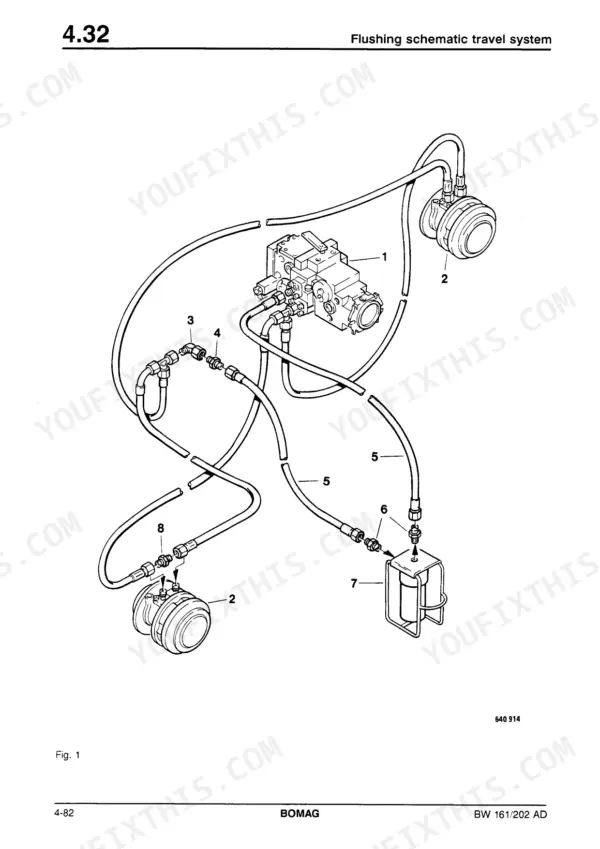
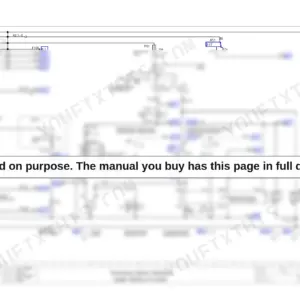
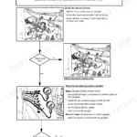
Bomag put its own part number on this book: 008 191 32, the 318-page factory repair manual for the BW 161 AD and 202 AD tandem vibratory rollers. Hydraulic schematics trace the closed-loop travel and vibration circuits, wiring diagrams map the relay board and monitoring module, and troubleshooting charts walk travel, vibration, and steering faults back to a testable cause. Sealing procedures take the travel and vibration pump apart valve by valve, so you can reseal a leaking control unit instead of replacing the whole pump, then flush the circuit afterward. Set charge pressure inside the 18 to 22 bar window, confirm 390 to 410 bar on the high pressure test, and torque the coupling screws to 90 Nm. A guessed relief pressure can cook a pump in one shift. Bookmarked and text-searchable, it rides on whatever screen you carry to the machine.
Complete the set for your BW 161 AD, BW 202 AD
What's Inside This Bomag BW 161 AD, BW 202 AD Repair Manual
| System | Pages | Key Topics |
|---|
| General Information | 9-26 | Safety Regulations, Technical Data, Torques, Connecting Points, Special Tools |
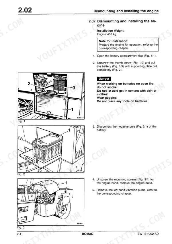
| Engine | 27-42 | Checking Diesel Engine Speed, Dismounting and Installing the Engine, Preparing the Engine for Operation |
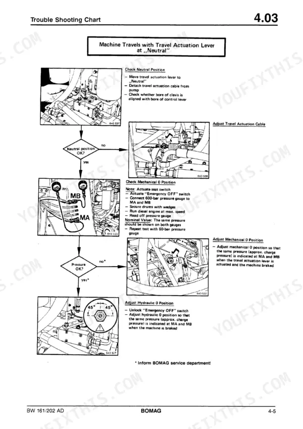
| Travel System | 43-134 | Pressure Tests in the Travel System, Travel Pump High Pressure Test, Trouble Shooting Chart, Dismounting and Installing the Travel Motor, Repair Survey, Repairing the Travel Motor |
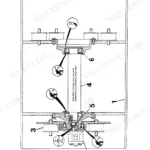
| Vibration | 135-230 | Checking the Speed of the Exciter Shaft, Trouble Shooting Chart, Dismounting and Installing the Vibration Pump for the Front Drum, Exchanging the Coupling for the Vibration Pump |
| Steering | 231-266 | Checking, Adjusting the Steering Pressure, Trouble Shooting Chart, Dismounting and Installing the Steering Cylinders, Repairing the Steering Cylinder |
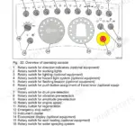
| Electric System | 267-304 | Important Electric Symbols and Designations, Overall View of Instrument Panel, Current Supply, Fuses, Starting, Charge and Start Control, Brake, Brake Control |
| Circuit Diagrams | 305-318 | Wiring Diagramme, Hydraulic Schematic |
Quick Reference Specifications
| Specification | Value | Page |
|---|
| All Models |
| Solenoid coil current consumption | 1.23 A | p. 49 |
| Charge pressure | 18 ... 22 bar | p. 45 |
| High pressure | 390 ... 410 bar | p. 45 |
| Pressing force for brake assembly (Bomag-part-no. 058 152 38) | 35000 N (3.5 t) | p. 72 |
| Mounting screws for coupling | 90 Nm | p. 152 |
| Mounting nuts for drive disc | 420 Nm | p. 153 |
| Constant pressure for bleeding | 20-22 bar | p. 221 |
| Maximum pressure during bleeding | 100 bar | p. 222 |
| Terminal #6 voltage (seat contact switch closed) | Approx. +6.7V | p. 299 |
| Terminal #7 voltage (left hand seat contact switch closed) | Approx. +6.7V | p. 299 |
| BW 161 AD |
| Operating weight (Cece), BW 161 AD | 9087 kg | p. 15 |
| BW 202 AD |
| Operating weight (Cece), BW 202 AD | 10077 kg | p. 15 |