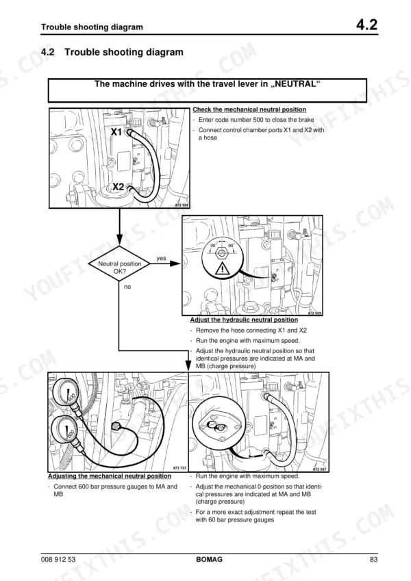
A tandem roller that creeps in neutral or loses vibration mid-mat leaves a whole paving train standing, and the Bomag BW 180 AD repair manual PDF (OEM 008 912 53) is the factory answer: 326 pages on the tandem vibratory roller, from pressure tests to full drum teardown. Flushing schematics map the front and rear drum drives and the vibration circuit, while the troubleshooting diagram traces each symptom back to the failed component. Supplier documentation fills the back half of the book, rebuilding the A4VG and A10VG travel pumps, MS/MSE drum drive motors and the A2FM 32 vibration motor down to the rotary group. Check the steering circuit against its 200 ±10 bar nominal, and confirm the brake releases at 26 bar before you condemn the drive. Every hour this machine sits, the lift waits. Bookmarked and text-searchable, the PDF puts each of those sections one tap away.
What's Inside This Bomag BW 180 AD Repair Manual
| System | Pages | Key Topics |
|---|
| General | 5-14 | Safety Regulations, General Repair Instructions |
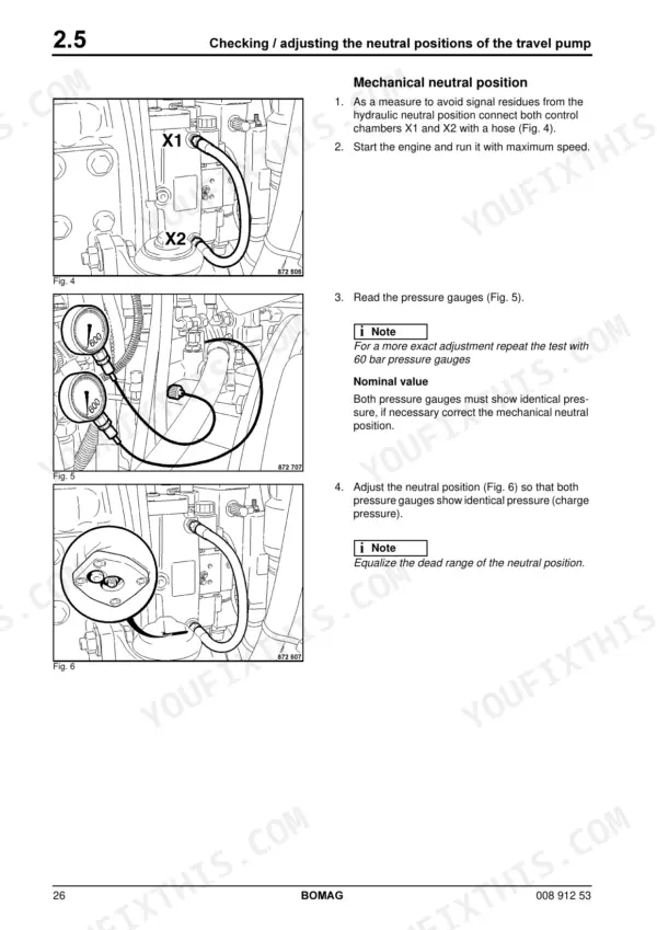
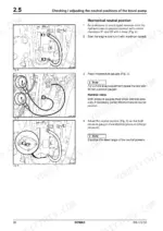
| Tests and Adjustments | 15-54 | Technical Data, Special Tools, Checking the Rotation Speeds, Pressure Tests in the Travel Circuit, Checking / Adjusting the Neutral Positions of the Travel Pump |
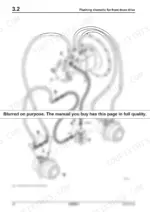
| Flushing | 55-80 | Special Tool, Flushing Shematic for Front Drum Drive, Flushing Schematic for Rear Drum Drive System, Flashing the Travel Circuit, Flushing Schematic for Vibration Drive |
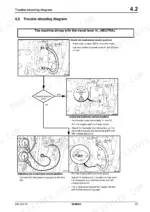
| Trouble Shooting | 81-102 | General Notes, Trouble Shooting Diagram |
| Drum | 103-142 | Special Tools, Repair Overview for Drum, Removing and Installing the Drum, Removing and Installing the Vibrator Unit on the Drum Drive Side |
| Pivot Steering | 143-152 | Removing Repairing and Installing Pivot Steering, Repairing the Oscillation Joint |
| A4VG | 155-200 | Sectional View, Drive Shaft, Boost Pump, Control Piston Cover, Valves, Rotary Group |
| A10VG | 201-254 | Sectional View, Seal Kits and Sub-Assemblies, Sealing of the Pressure Cut-Off Valve, Control Units (Hd-Ep Old and New, HD New, EP New), Pump Disassembly, Assembly Guidelines for Tightening Torques, Mechanical and Hydraulic Zero Position Adjustment |
| MS/MSE 02 to 18 | 255-304 | Brake Piston, Bearing Support, Brake Shoes, Cam, Cylinder Block Assembly, Valving |
| Vibration Motor A2FM 32 | 305-326 | Housing, Connecting Plate, Valve Plate, Drive, Drive Shaft |
Quick Reference Specifications
| Specification | Value | Page |
|---|
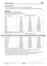
| Tightening torque for M4 screw (8.8) | 3 Nm (2 ft-lb) | p. 11 |
| Tightening torque for M5 screw (8.8) | 6 Nm (4 ft-lb) | p. 11 |
| Pressure test in steering circuit nominal value | 200 ±10 bar | p. 36 |
| Minimum step current | 350 mA | p. 49 |
| Brake releasing pressure nominal value | 26 bar | p. 84 |
| Operating weight (Cece) with ROPS-cabin | 11870 kg | p. 16 |
| Engine Rated power ISO 9249 | 76 kW | p. 16 |
| Engine Nominal speed | 2500 rpm | p. 16 |
| Travel pump High pressure (pressure limitation) | 440 bar | p. 17 |
| Travel pump Charge pressure | 26 bar | p. 17 |
| Vibration pump Start-up pressure | 380 bar | p. 17 |
| Hydraulic oil filling capacity | 60 l | p. 18 |