
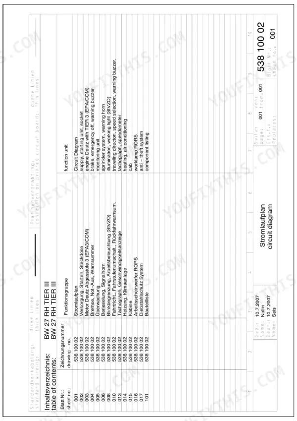
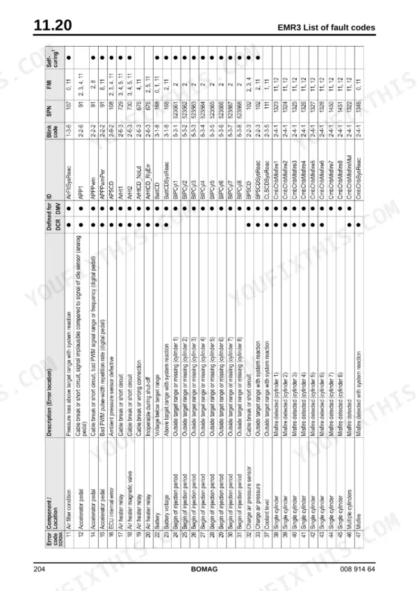


Directing every overhaul and maintenance phase for the rubber tire roller, this 776-page Bomag BW 27 RH service manual pdf (OEM ID 008 914 64) keeps your compaction crew moving on the mat. The technical reference maps out the electrical architecture with E-Plan wiring diagrams, EMR3 system pinouts, and module calibrations. Fluid power receives heavy coverage, tracing travel pump routing through detailed hydraulic schematics alongside external gear pump diagnostics. Lock down the M22x1.5 wheel nuts to a strict 500-600 Nm and verify tire inflation holds between 2 and 8.1 bar before sending the machine back for another pass. Guessing at travel circuit pressures on a roller this heavy just buys you a towed unit and a ruined shift. Download the bookmarked, text-searchable file, print the exact fault code tables you need, and let the pages get dirty on the bench while you clear the lane.
Complete the set for your BW 27 RH
- Operator Manual: Bomag BW 24 RH, 27 RH, 24/27 RH Operator Manual
- Operator Manual: Bomag BW 27 RH Rubber Tire Roller Operator Manual
What's Inside This Bomag BW 27 RH Manual
| System | Pages | Key Topics |
|---|---|---|
| General | 7-32 | Introduction, Safety Regulations, Tightening Torques |
| Pneumatic Tires Rollers | 33-36 | Rubber Tire Roller |
| Technical Data | 37-42 | Operating Weight, Travel Speed, Engine Type, Filling Capacities, Steering Angle, Tire Pressure |
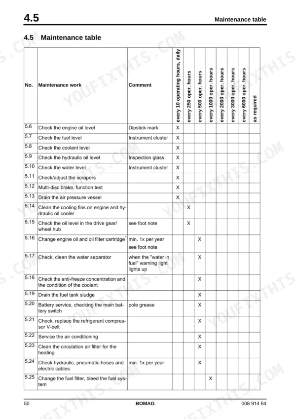
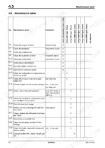
| Maintenance | 43-52 | Fuels and Lubricants, Table of Fuels and Lubricants, Running-In Instructions, Maintenance Table |
| Caddy Wiring Diagrams | 53-60 | Understanding Circuit Diagrams, Circuit Symbols in the Circuit Diagram, Identification of Switch Blocks in the Caddy Wiring Diagram |
| E-Plan Wiring Diagrams | 61-74 | Understanding Wiring Diagrams, Circuit Symbols in the Circuit Diagram, Identification of Switch Blocks in the Wiring Diagram |
| Electrics | 75-138 | Designation of Components in the Wiring Diagram, Terminal Designations in Wiring Diagram, Battery Ground and Analog Ground, Current and Voltage, Resistance |
| Electronic Modules | 139-160 | Module Description A04, Electric Module A72, Old Design, Electric Module A108 |
| Module Description A100 | 161-164 | Steering Column Locking Module, A100 |
| Speedometer Module | 165-168 | Self-Teaching Mode, Display Self-Test, Measuring Mode, Manual Display Test, Teach Mode |
| Engine Electrics | 169-296 | EMR3 System Components, Pin Assignment of Engine Control EDC16 / EMR3, Rotary Speed Sensor for Camshaft, Rotary Speed Sensor for Crankshaft, Rail Pressure Sensor |
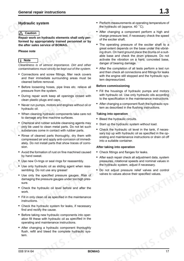
| Hydraulics | 297-334 | Hydraulic Circuit, Travel Pumps, A4VG105 Da, Troubleshooting Axial Piston Pumps, External Gear Pumps, Travel Motor, A6VM 107HA2R1, Trouble Shooting |
| Brake | 335-348 | Brake System, Stopping the Machine, Operating the Parking Brake, Driving the Machine / Braking the Machine, Multi-Disc Brake, Function Test, Towing in Case of an Engine Failure |
| Pneumatics | 349-360 | Pneumatic System, Operating the Tire Inflation System, Draining the Air Pressure Vessel, Changing the Air Drier for the Brake System, Checking the Supply Lines for the Compressor |
| Engine | 361-408 | Lubrication Oil Circuit Tcd 2012 / 2013, Coolant Circuit Tcd 2012 / 2013, Fuel System Tcd 2012 / 2013, Deutz Common Rail Injection System for Tcd 2012 / 2013 |
| Air Conditioning System | 409-452 | Physical Basics, Refrigerant R134a, Compressor Oil / Refrigeration Oil, Working Principle of the Air Conditioning System, Monitoring Devices, Components |
| Replacing the Cab Window Panes | 453-462 | Assembly of Window Panes, Special Tools, Cabin Windows, Auxiliary Materials, Removing and Installing the Window Pane |
| Front Axle | 463-494 | Repair Overview for Front Axle, Dismantling the Front Axle, Assembling the Front Axle |
| Suppliers Documentation | 495-700 | Travel Pump, Travel Motor, Travel Gear, Steering Valve |
| Circuit Diagrams | 701-776 | Hydraulic Diagram 538 110 00, Pneumatic Diagram 538 120 00, Wiring Diagram 538 100 02, Wiring Diagram 27 |
Quick Reference Specifications
| Specification | Value | Page |
|---|---|---|
| Tightening torque for M12x1.5 wheel nuts | 100 Nm | p. 29 |
| Tightening torque for M14x1.5 wheel nuts | 150 Nm | p. 29 |
| Air pressure min./max. | 2-8.1 bar (29-117.5 psi) | p. 39 |
| Valve clearance (Intake) | 75°+10° | p. 51 |
| Valve clearance (Exhaust) | 120°+10° | p. 51 |
| Factory specification for resistance (rotor) | 2.8 to 5 OHM | p. 283 |
| Factory specification for resistance (stator) | Less than 1 OHM | p. 284 |
| Return flow filter fine filter rating | 12 µ | p. 330 |
| Bypass valve opening pressure differential | 3.5 bar | p. 330 |
| Cross-flushing check valve pressure | 6 bar | p. 330 |
| Differential pressure switch (B22) switching pressure | 2.5 bar | p. 330 |
| Oil inlet for brake cooling | 6 bar | p. 341 |
Bomag BW 27 RH Common Problems This Manual Covers
Bomag BW 27 RH pulling to one side and leaving uneven mat finish
Check tire pressures across the front and rear axles. Inflate all tires strictly between 2-8.1 bar (29-117.5 psi) as shown on page 39. Inspect the wheel nuts on page 29 and torque any M12x1.5 studs to 100 Nm to prevent hub damage.
Manual Section: Technical Data p. 39Parking brake fails to release or holds the machine back when shifting out of neutral
Inspect the multi-disc brake release circuit. Verify the compressed air accumulator pressure for the brake system reaches 5.7 bar as detailed on page 344. If air pressure is correct, check the hydraulic side and confirm the oil inlet for brake cooling maintains 6 bar.
Manual Section: Brake p. 344Battery charge control light stays illuminated during high idle operation while rolling the mat
Test the generator pre-exciter circuit. Measure the internal resistance across the rotor; page 283 shows it must read 2.8 to 5 OHM. Check the stator resistance on page 284, which should be less than 1 OHM. Replace the carbon brushes if they measure under 5 mm.
Manual Section: Engine Electrics p. 283Air conditioning compressor cuts out and engine cooling fan squeals under heavy compaction load
Inspect the ribbed V-belt for glazing or cracking. Measure the belt depth and replace it if worn past the 3 mm limit shown on page 386. Adjust the tensioner until you achieve a V-belt deflection of 10 to 15 mm as specified on page 424.
Manual Section: Air Conditioning System p. 424Frequently Asked Questions
How do I delete passive faults from the first fault log on the EMR3 engine control unit?
To clear fault log 1, turn the ignition OFF, then press and hold the diagnostics button. Switch the ignition back on while holding the button. Release the button after approximately 10 seconds. The deletion process is confirmed by three short flashing pulses. p. 198
What is the tightening torque for M10 screws with strength class 8.8 on a Bomag BW 27 RH?
For screws with a metric unified thread and a strength class of 8.8, the tightening torque for an M10 screw is 50 Nm. p. 28
What is the correct valve clearance for the intake valves on the TCD 2012 / 2013 engine?
The valve clearance for the intake valves on the TCD 2012 / 2013 engine is 0.3 mm. p. 39
What is the engine oil capacity for the Bomag BW 27 RH?
The engine oil capacity for the BW 27 RH is approximately 15.5 litres. p. 39
What is the correct tightening torque for the M14x1.5 wheel nuts on a Bomag BW 27 RH?
The tightening torque for M14x1.5 wheel nuts is 150 Nm. p. 29
Is this Bomag BW 27 RH manual a PDF I download?
Instant PDF download. You get the full 776-page searchable Service Manual immediately after payment. Open it on your laptop, tablet, or phone right in the shop.
Can I print specific sections of this Bomag BW 27 RH Service Manual?
Yes. Print the sections you need to take out to the shop for your own use. Standard letter or A4 paper works.
Reviews
There are no reviews yet.