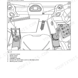
When a BW 75 H stops shaking mid-pass, the fix usually lives somewhere in these 122 pages: this Bomag BW 75 H service manual PDF (OEM ID 008 915 16) is the factory repair book for the double vibratory roller, from safety regulations through full drum and travel drive repairs. Hydraulic diagram 820 601 13 and wiring diagram 820 031 19 map every line and wire in the machine, and a dedicated troubleshooting chapter works the vibration drive fault by fault. Repair chapters take you through the travel cable, drum bearings, exciter shaft, travel pump, and drum drive, each closing with the correct adjustment. Set exciter shaft end float between 0.8 and 1.6 mm, and heat the drive gears to 200 degrees C before pressing them onto the drum axles. Every hour spent hunting a spec is an hour the roller sits. Bookmarks in this text-searchable PDF put the section you need two taps away.
What's Inside This Manual
| System | Pages | Key Topics |
|---|
| General | 5-24 | Introduction, Safety Regulations, General Repair Instructions |
| Technical Data | 25-28 | Weights, Dimensions, Travel Performance, Engine, Vibration System, Capacities |
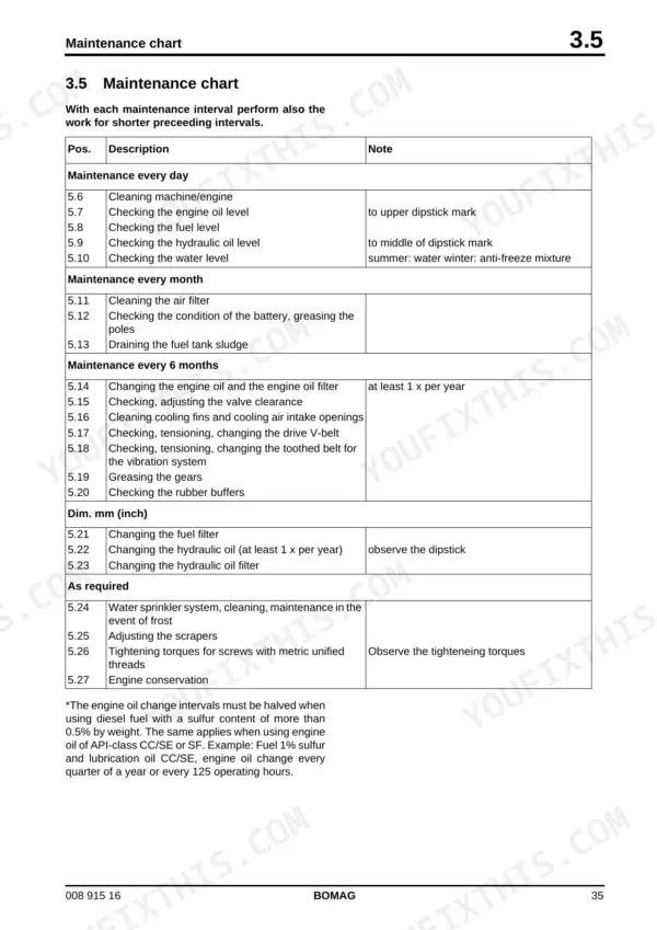
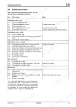
| Maintenance | 29-36 | Fuels and Lubricants, Table of Fuels and Lubricants, Running-In Instructions, Maintenance Chart |
| Tests and Adjustments | 37-44 | Special Tools, Checking the Rotation Speeds, Travel Pump Pressure Test |
| Trouble Shooting | 45-48 | Trouble Shooting in Vibration Drive |
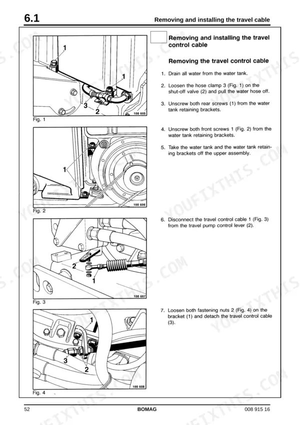
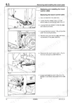
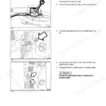
| Removing and Installing the Travel Cable | 49-56 | Travel Control Cable, Water Tank Removal, Steering Rod, Cable Adjustment |
| Removing and Installing the Travel Cable (C4) | 57-62 | Safety Control C4, Contact Button, Releasing Lever, Cable Installation |
| Removing and Installing the Drum | 63-76 | Drive Gear, Vibration Drive, Upper Structure, Drum Bearings |
| Repair Drum | 77-86 | Exciter Shaft, Vibration Bearing, Drive Flange, End Float Measurement |
| Travel Pump | 87-96 | Charge Pressure Relief Valve, Rotor, Swash Plate, Radial Seal |
| Drum Drive | 97-108 | Travel Motor, Valve Housing, Gear Set, Balance Plate |
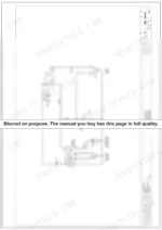
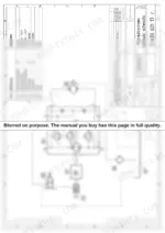
| Circuit Diagrams | 109-122 | Hydraulic Diagram 820 601 13, Wiring Diagram 820 031 19 |
Quick Reference Specifications
| Specification | Value | Page |
|---|
| Operating temperature of the hydraulic oil | 40 °C | p. 13 |
| Exciter shaft end float | 0.8 mm to 1.6 mm | p. 47 |
| Heating temperature for drive gears | 200 °C | p. 71 |
| Axial play | 0.8 mm - 1.6 mm | p. 78 |
| Battery | 12V/55Ah | p. 118 |
| Hauptsicherung (Fuse, main) | 20A | p. 118 |
| Meldeleuchte Ladekontrolle (Indicator light, charge control) | 0,22A | p. 119 |
| Operating weight (Cece) | 1015 kg | p. 26 |
| Working width | 750 mm | p. 26 |
| Rated power ISO 9249 | 6.2 kW | p. 26 |
| Nominal speed | 3100 rpm | p. 26 |
| Fuel tank capacity | 5.5 L | p. 27 |