Bomag wrote this repair manual, publication 0852636, for the BW124D smooth drum, the BW124PD padfoot and the BW124PDB with the leveling blade, serial number prefix A219, and the PDF runs 262 pages. The book is built system by system. Transmission is the biggest chapter at pages 127 to 178, with travel pump repairs and the procedure for flushing the circuit after a failure, then steering on 183 to 204, vibration on 205 to 226 and the leveling blade on 237 to 254. The Deutz F3L1011 gets its own removal and installation chapter, and specifications start on page 13. Nominal values are printed where you need them: 180 bar starting and 60 bar operating pressure on the vibration pump, 200 bar at the vibration valve on page 222, steering relief at 1,850 psi. Guess those and you condemn a pump that was fine. Forty four bookmarks and a live text layer put the right page one tap away.
What's Inside This Repair Manual
| System | Pages | Key Topics |
|---|
| Introduction | 7-12 | Operating Instructions, Maintenance Procedures, Repair Procedures, Name Plate / Serial Number Plate, Serial Number |
| Specifications | 13-36 | Frame and Hitch Specifications, Engine Specifications, Electrical Specifications, Transmission System Specifications, Brake System Specifications |
| Operation | 37-58 | Operating Controls and Indicators, Operating Precautions |
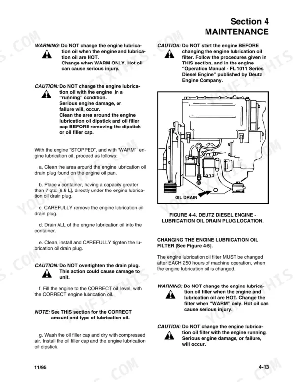
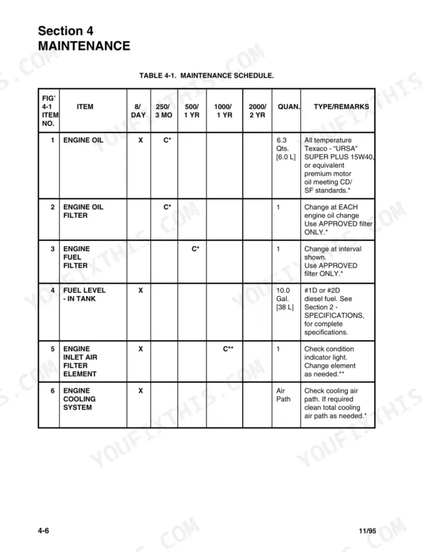
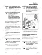
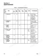
| Maintenance | 59-90 | Maintenance Schedule, Engine Maintenance, Hydraulic System Maintenance |
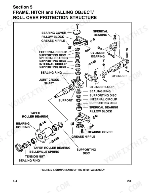
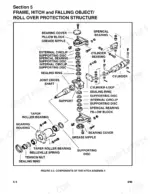
| Frame, Hitch and Falling Object/Roll Over Protection Structure | 91-100 | Description of Frames and Hitch, Removal of Hitch Assembly |
| Engine | 101-106 | Removal of Engine Assembly, Installation of Engine Assembly |
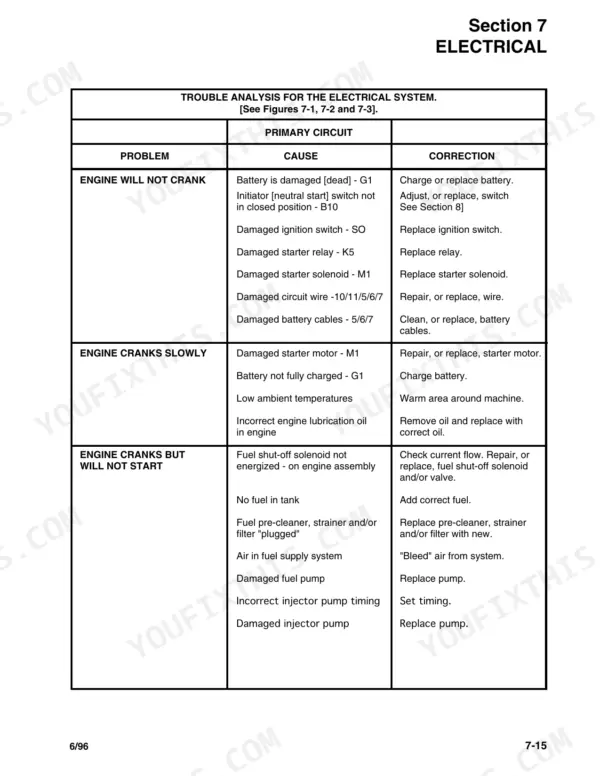
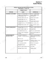
| Electrical System | 107-126 | Electrical System Major Components, Trouble Analysis for Electrical System |
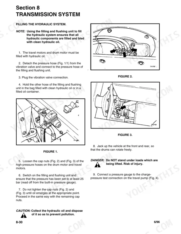
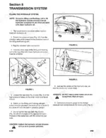
| Transmission System | 127-178 | Travel Pump Repairs, Flushing Transmission System, Trouble Analysis for Transmission System |
| Brake System | 179-182 | Dynamic Braking, Basic Operation, Secondary/Parking Brake System, Hydraulic System Control Valve Assembly |
| Steering System | 183-204 | Steering System Operation, Steering Control Unit Repairs, Trouble Analysis for Steering System |
| Vibration System | 205-226 | Drum and Vibration Operation, Repairing the Drum, Trouble Analysis for Drum and Vibration |
| Control Systems | 227-236 | Governor Control System, Travel Control System, Trouble Analysis for Control Systems |
| Optional Equipment | 237-254 | Leveling Blade System, Leveling Blade Cylinder Repairs, Trouble Analysis for Leveling Blade |
| Special Tools | 255-262 | Vibration Read Frequency Meter, Filling and Filtering Unit, Mounting Jig, Centering Jig, Puller, Pin Wrench, Centering Plate, Mounting Tool |
Quick Reference Specifications
| Specification | Value | Page |
|---|
| Hydraulic Vibrator Pump Output Rate and Speed | 5.2 GPM [20 lpm] @ 2500 RPM | p. 20 |
| Hydraulic Vibrator Motor Input Rate | 5.2 GPM [20 lpm] @ 4000 psi. [276 bar] | p. 23 |
| Hydraulic system oil capacity | 8.0 Gal. [30.3 L] | p. 65 |
| Hydraulic oil filtration | 10 micron | p. 79 |
| Weight of travel pump | 50 kg | p. 131 |
| Vibration pump high pressure nominal value | 180 bar (starting pressure), 60 bar (operating pressure) | p. 222 |
| Vibration valve nominal value | 200 bar | p. 222 |
| Fuel Tank Capacity | 10 Gallons | p. 16 |
| Battery Voltage | 12 Volts | p. 17 |
| Transmission System Oil Capacity | 8.0 Gallons | p. 18 |
| Steering Relief Pressure | 1,850 psi | p. 20 |
| Drum Width | 47.0 in. | p. 22 |