
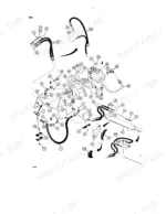
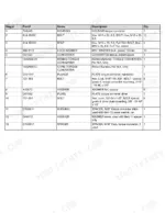
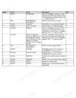
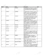
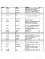
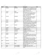
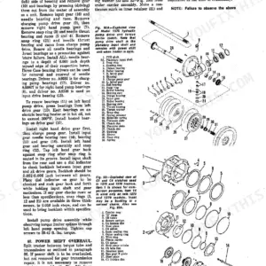
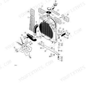
Part of the Case Parts Manuals.
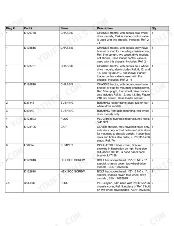
All 755 pages of this Case 580 Super E, Construction King, Loader Backhoe Parts Catalog PDF (OEM #Bur 8-1833) focus on one thing: getting the exact replacement components for your machine without the guesswork. You get highly detailed exploded views of the entire equipment, complete with factory part numbers and cross-references for every single bolt, seal, and major assembly. Open up the electrical, hydraulic, and drivetrain sections to find precise component identification that eliminates ordering mistakes. Need to rebuild the loader lift cylinder? Grab seal kit G109460, and make sure you order the J904374 fuel lift pump assembly before tearing into the fuel system. Stop wasting days waiting on returns for the wrong items. Download this bookmarked digital reference straight to your phone, look up the exact number you need, and get your iron back in the dirt.
What's Inside This Case 580 SUPER E, Construction King Parts Manual
| System | Pages | Key Topics |
|---|---|---|
| General | Parts Ordering Information, Serial Number and Pin Location, Pictorial Section Index, And Revision Log | |
| Engine | Radiator, Fan and Mounting, Air Cleaner and Intake, Engine Block, Cylinder Head, Pistons, Crankshaft, And Oil Pump Parts | |
| Fuel System | Fuel Tank and Lines, Throttle Control Linkage, And Fuel Injection System Parts for the 4T-390 and 4-390 Diesel Engines | |
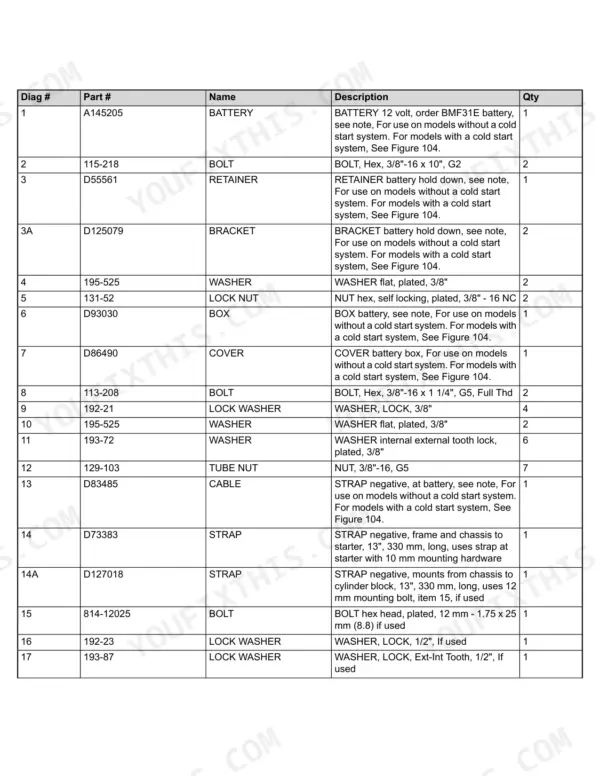
| Electrical System | Starter, Alternator, Compressor, Wiring Harness, Lights, Instruments, And Battery Parts | |
| Steering | Steering Wheel and Column, Steering Hydraulic Circuit, Steering Control and Relief Valves, And Steering Cylinder Parts | |
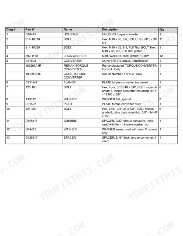
| Power Train | Rear Wheels and Tires, Torque Converter and Housing, Power Shuttle, Transmission, And Axle Parts | |
| Brakes | Brake Pedals and Mounting, Brake Master Cylinder, And Brake Circuit Parts | |
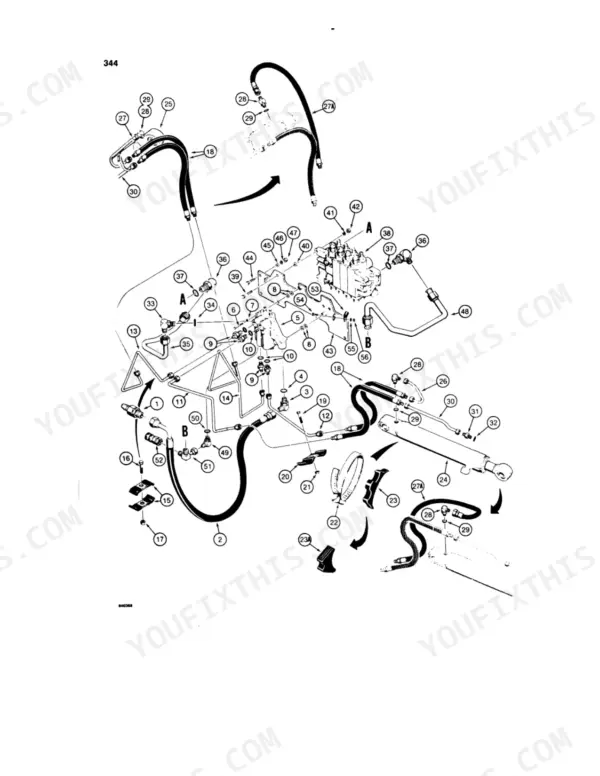
| Hydraulics | Equipment Hydraulic System, Reservoir, Loader Control Valve, Hydraulic Pump, And Cylinder Parts | |
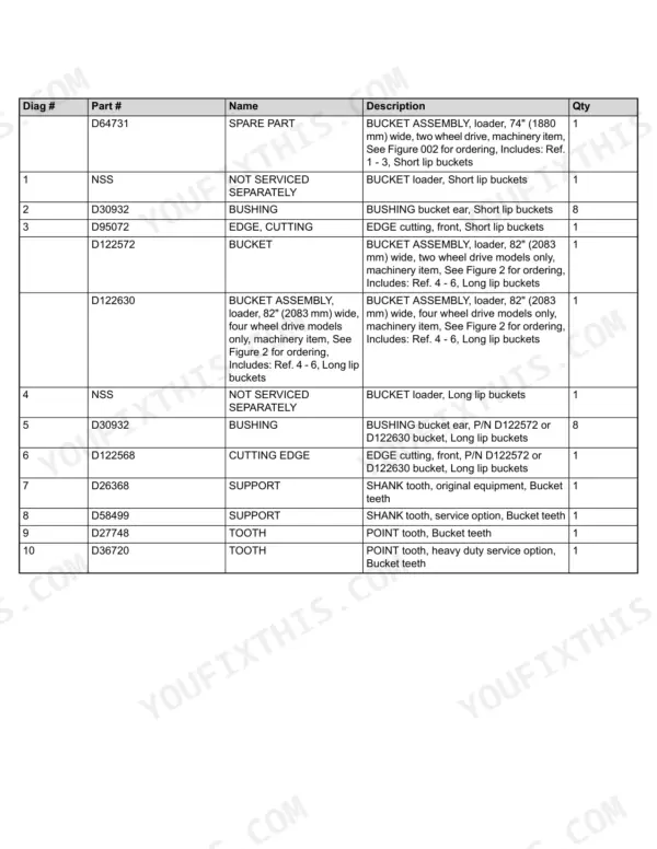
| Chassis Attachments | Loader Frame, Bucket, Cutting Edge, Shank and Point Teeth, Tower Control, And Backhoe Attachment Parts |
Quick Reference Specifications
| Specification | Value | Page |
|---|---|---|
| Cylinder seal kit (Loader Lift Cylinder) | G109460 | p. 513 |
| Disc friction, internal tooth (Power Shuttle Forward Clutch) | D70672 | p. 215 |
| Hydraulic pump assembly (Webster No. 152-45207-115) | D126580 | p. 430 |
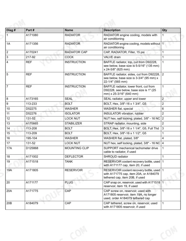
| Radiator Cap Pressure | 15 psi | p. 11 |
| Thermostat Water Temperature | 95 degree C, 203 degree F | p. 43 |
| Engine Oil Pan Bolt (Hex) | M8 x 30, 8.8 | p. 41 |
| V-Belt (Water Pump) | 3.56 mm W x 1574.80 mm L, 8 Ribs | p. 32 |
| Battery Voltage | 12 volt | p. 113 |
| Circuit Breaker (Main) | 40 amperes | p. 114 |
Case 580 SUPER E, Construction King Common Problems This Manual Covers
Case 580 Super E hydraulic cylinder seal kit part number for boom, arm, and loader cylinders
Check the hydraulic parts diagram for the exploded view of your cylinder assembly. The loader lift cylinder seal kit is listed as part #G109460 on page 513. Cross-reference the parts index against your tractor's PIN before ordering to confirm the kit matches your serial number range.
Manual Section: Hydraulics p. 350Hydraulic pump assembly part number keeps getting ordered wrong for the equipment and steering circuit
Verify the exploded view on page 430 before ordering. The equipment and steering hydraulic pump is part #D126580, built on a Webster No. 152-45207-115 base, and the listing covers references 2 through 22 in that assembly. Match the reference number on the diagram to your specific mounting configuration first.
Manual Section: Hydraulics p. 430Power shuttle forward clutch friction disc part number needed for a full pack rebuild
Pull up the power train drivetrain diagram starting to locate the clutch pack assembly. The internal tooth friction disc is part #D70672, and the parts list on page 215 shows 7 discs required per pack. Order the full quantity at once since partial packs mix old and new plate thickness.
Manual Section: Power Train p. 215Fuel lift pump and mounting gasket part numbers for the Cummins BT4/BT6 engine
Reference the fuel system parts diagram on page 76 to confirm the fuel lift pump assembly, listed as part #J904374 on page 81. The mounting gasket is a separate line item, part #J904044, quantity 1 per pump. Order both together since the gasket is not bundled with the pump assembly.
Manual Section: Fuel System p. 81Injection pump component numbers for a CAV/Stanadyne fuel system rebuild
Check the fuel system section beginning on page 74 and locate the injection pump listing on page 86. The Lucas DPA3042/00996 injection pump assembly is part #J908645. Confirm the pump model stamped on your unit matches this listing before ordering, since earlier serial ranges may use a different pump casting.
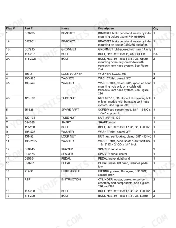
Manual Section: Fuel System p. 86Brake master cylinder hydraulic circuit parts differ before and after a certain tractor pin
Open the brake parts diagram on page 331 and check which pin break applies to your machine. The manual splits this circuit into two listings, one for tractors before pin 9869266 and one for pin 9869266 and after, so pull your tractor's serial tag first. Order from the matching listing only, since the two circuits are not interchangeable.
Manual Section: Brakes p. 331Frequently Asked Questions
How to reset the solenoid or electrical system?
The manual lists various solenoids and electrical components by part number, such as 'SOLENOID electrical' (Part # A77311) and 'SOLENOID clutch cutout' (Part # D134742). However, it does not provide a general procedure for resetting the solenoid or the entire electrical system. p. 120
How to reset the machine after shutting off unexpectedly?
The manual contains various warning decals related to operation and maintenance, such as 'DECAL Caution, stop engine before dismounting, safety warnings' (Part # 321-6262). However, it does not provide a specific procedure for resetting the machine after an unexpected shutdown. p. 751
What are the replacement specifications for the Fuel lift pump (Cummins BT4/BT6 with seal and sill)?
The fuel lift pump assembly is identified by Part # J904374. Its mounting gasket is Part # J904044. The manual does not provide further replacement specifications like torque values or specific tools for installation. p. 81
What are the replacement specifications for cylinder seals and rod gaskets for hydraulic cylinders?
For the G105756 Loader Lift Cylinder, a GASKET KIT (Part # G109460) is available, which includes various seals such as the 'WIPER piston rod, outer' (Part # D95143) and 'SEAL u cup, with O ring, piston rod, wide' (Part # G107922). Similar gasket kits are available for other hydraulic cylinders, containing the necessary seals and rings for repair. p. 514
What is the part number for a new starter motor assembly?
A new starter motor assembly is listed with Part # A170746. Its description specifies it as a 'STARTER ASSEMBLY, new, Nippondenso No. 5-128000-395'. p. 92
Is this manual digital?
Instant PDF download. You get the full 755-page searchable Parts Catalog immediately after payment. Open it on your laptop, tablet, or phone right in the shop.
Can I print specific sections of this manual?
Yes. The PDF has no DRM restrictions, so print any page or section you need for your shop. Works with any standard printer.


Reviews
There are no reviews yet.