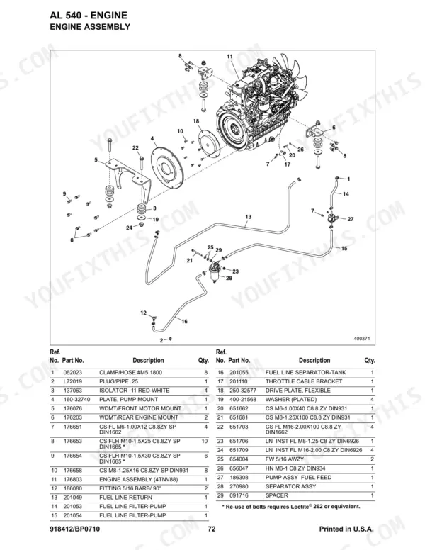
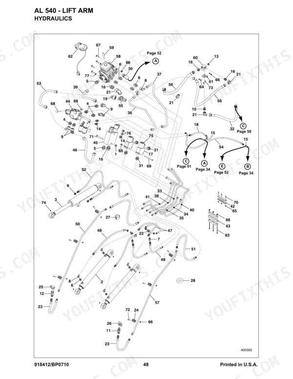
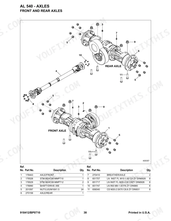
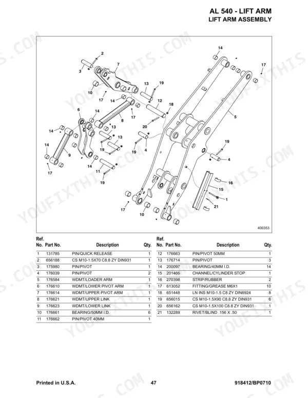
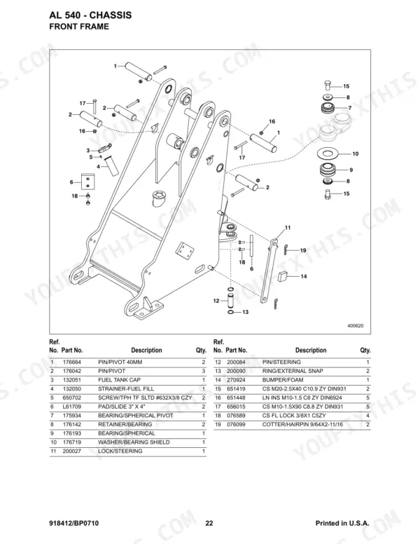
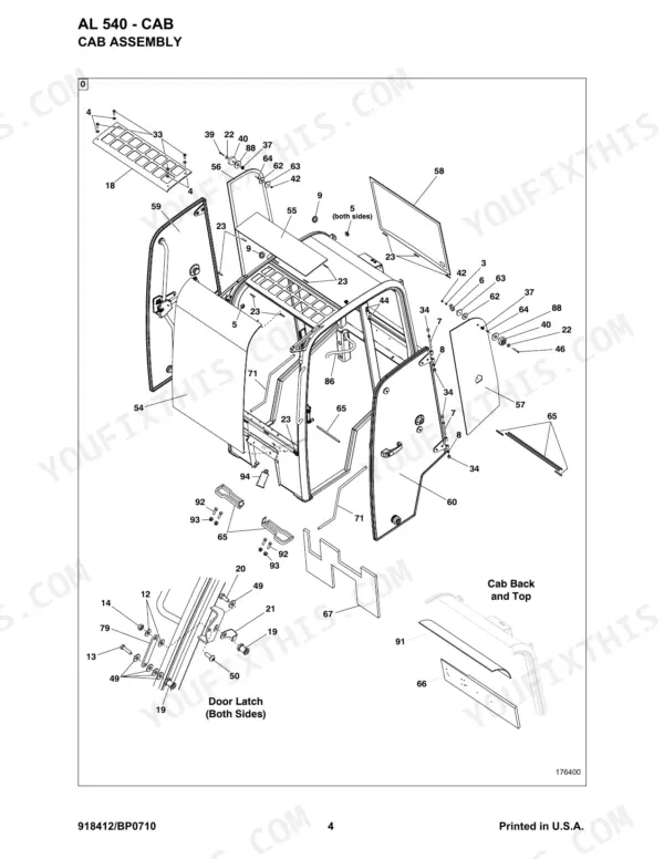
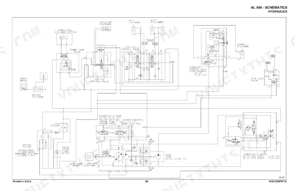
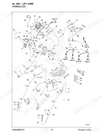
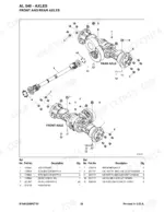
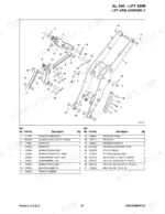
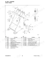
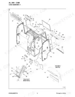
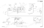
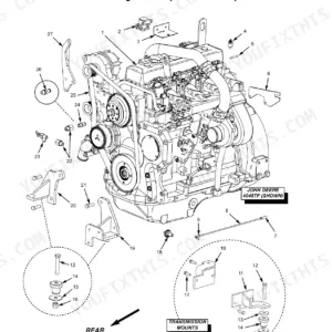
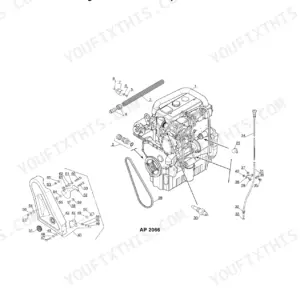
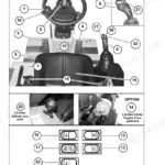
From the cab, ROPS and frames through the axles, lift arm, hydraulic cylinders and a full engine breakdown, the Gehl AL 540 parts manual PDF maps this articulated loader assembly by assembly across 128 pages under publication number 918412. Exploded views tie each callout to a Gehl part number, so the control valve, axial piston pump, bent axis motor and Power-A-Tach cylinder break down to the last seal ring and fitting. Hydraulic and electrical schematics trace the complete harness plus the steering column, chassis, engine and cab circuits, and a numerical index lets you work backward from the number on a worn part. When the pump relief valve goes, order 204466, the 450 bar unit, and add return filter 274912 to the same order. A loader on blocks can sit for days over one part number. Bookmarks split the file by system and the text layer is searchable, so you reach the right exploded view in a click or two.
What's Inside This Parts Manual
| System | Pages | Key Topics |
|---|
| Tools | 5 | Tools/Paint/Special Service Parts and Kits |
| Filters | 6-7 | All Filters, Return Filter - 274912 |
| Cab | 8-25 | Assembly, Doors - 270067 & 270071, Wipers, Heater, Completing Components, Mirrors, Steering Column - Deluxe, Operator’s Platform - Upper |
| Chassis | 26-37 | Front Frame, Rear Frame, Covers, Electrical (- Fuses, Headlights/Tail Lights, Field-Installed Road Light Kit, Battery Disconnect Kit, Backup Alarm Kit), Counterweight (Kit) |
| Controls | 38-41 | Differential Lock, Inching - Brake, Parking Brake, Throttle |
| Axles | 42-50 | Front and Rear Axles, Driveshaft, Internal Components, Wheels and Tires |
| Lift Arm | 51 | Assembly |
| Hydraulics | 52-63 | Hydraulic Tank, Hydraulic Drive, Power Steering, Control Valve, Auxiliary Valve, Axial Piston Hydraulic Pump |
| Hydraulic Cylinders | 64-67 | Lift Cylinder, Tilt Cylinder, Steering Cylinder, Power-A-Tach Cylinder |
| Attachments | 68-70 | All-Tach, Power-A-Tach, Field Installed Power-A-Tach Kit |
| Decals | 71-75 | Common Decals, ANSI Style Decals |
| Engine | 76-76 | |
| Cylinder Block | 77-77 | Assembly, Gear Housing, Flywheel Housing/Oil Pan, Intake Manifold, Camshaft |
| Gear Housing | 78-79 | |
| Cylinder Head and Cover | 80-98 | Exhaust Manifold |
| Fittings / O-Rings / Seal Rings | 99-101 | Hose / O-Ring Compatibility, Abbreviations and Descriptions for Fittings |
| Notes | 102 | |
| Schematics | 103-108 | FOPS, Power-A-Tach and Tail Light Electrical Schematics |
| Torque Specifications | 125-128 | Hydraulic Fittings, Coarse-Pitch Thread, Fine-Pitch Thread |
Quick Reference Specifications
| Specification | Value | Page |
|---|
| Relief Valve Pressure | 450 bar | p. 61 |