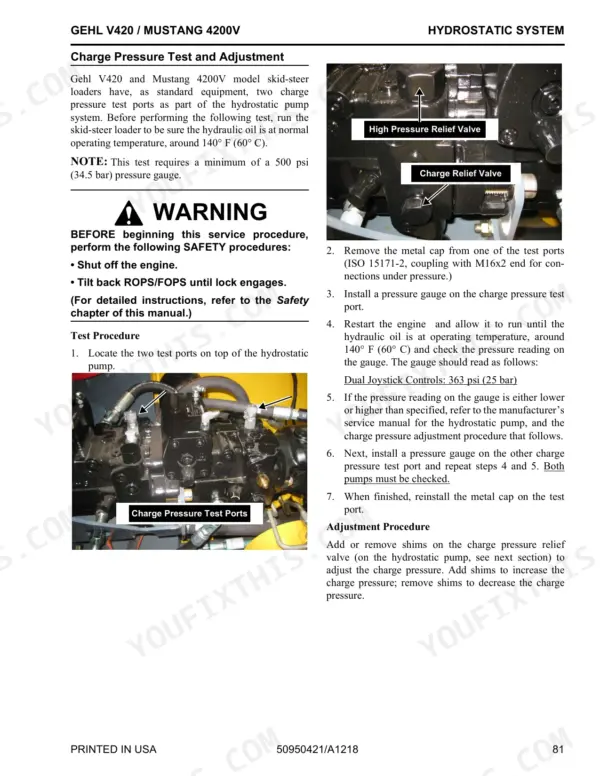
The 260-page Gehl V420, Mustang 4200V service manual PDF (Form No. 50950421) tears down one skid-steer loader sold under two badges, so whichever name sits on your decal, this factory book fits your machine. Hydrostatic drive gets serious attention, from charge pressure testing and pump relief valves through drive motor removal, with a combined hydrostatic and hydraulic schematic tracing every circuit. Wiring diagrams map the CAN network, power distribution panel and main control unit pins, while engine diagnostic fault code charts back up the troubleshooting guides when the loader throws a warning. Fill the crankcase to 9,5 liters after a filter change, then plan the next engine oil filter at 250 hours and the hydraulic filter element at 500. A loader on stands earns nothing while you chase one relief pressure. Bookmarked and text-searchable, this PDF finds the number and gets the machine cycling again.
What's Inside This Manual
| System | Pages | Key Topics |
|---|
| Specifications | 7-8 | Engine, Capacities, Electrical System, Hydraulic System, Tire Options, Buckets |
| Safety | 9-14 | Signal Words, Additional Safety Reminders, Potential Hazards, Machines Equipped with Air Conditioning, Mandatory Safety Shutdown Procedure |
| Lubrication | 15-20 | Hydraulic Oil Reservoir, Crankcase Oil, Chaincases, Grease Fitting Locations, Cooling System Drain Procedure |
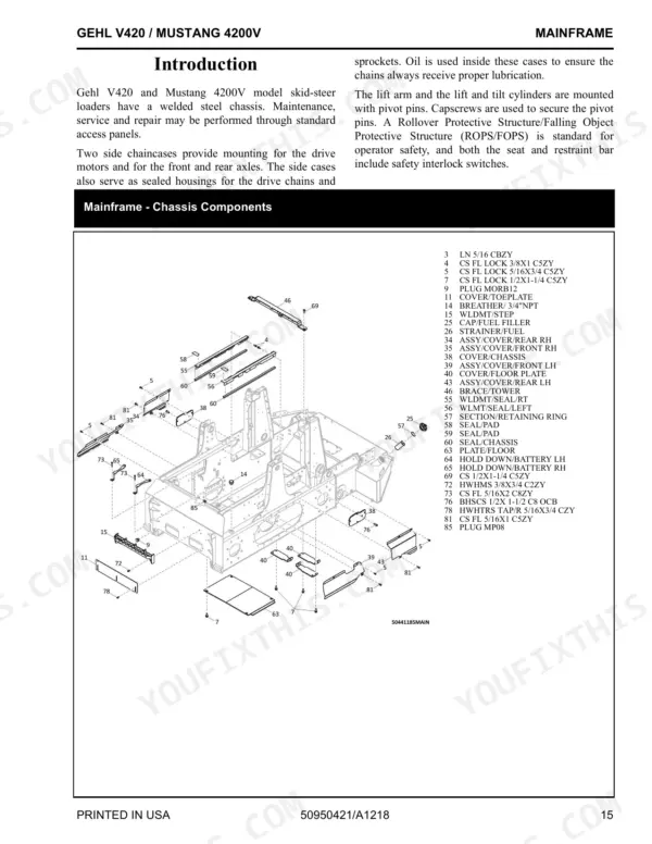
| Mainframe | 21-64 | Introduction, Mainframe - Chassis Components, Mainframe - Rear Grille Components |
| Wheel Drives | 65-72 | Introduction, Wheel Drive Components, Drive Chain Adjustment, Axle Housing Assembly Removal and Installation, Drive Chain Removal and Installation, Axle Assembly Components |
| Controls | 73-78 | Introduction, Control Locations, Wheel Drive Components |
| Hydrostatic System | 79-100 | Introduction, Hydrostatic Components, Charge Pressure Test and Adjustment, Hydrostatic Pump Relief Valves, Hydrostatic Pump Removal and Installation |
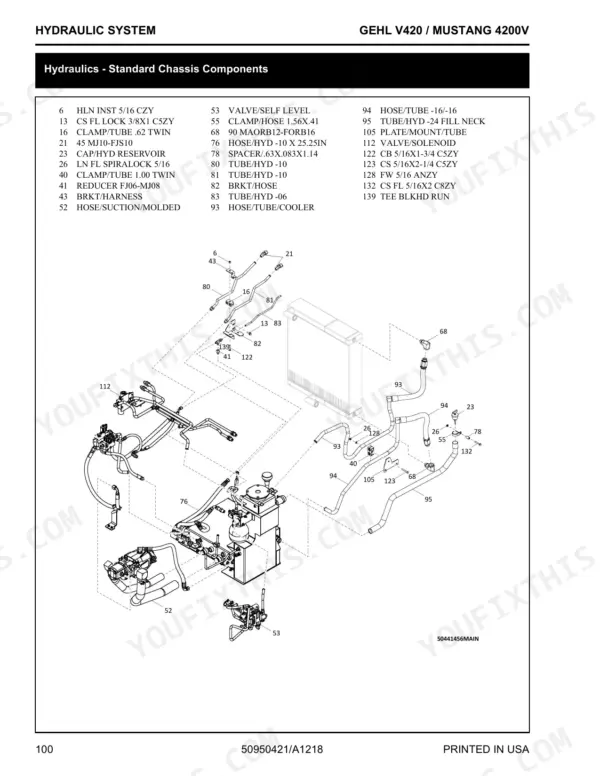
| Hydraulic System | 101-146 | Introduction, Hydraulics - Standard Chassis Components, Hydraulics - High-Flow Chassis Components, Hydraulics - Standard Auxiliary Lift Arm Components |
| Electrical System | 147-200 | Introduction, Power Distribution Panel Test and Operation, Fan Control Module Test, Chassis Electrical - Battery, Chassis Electrical - Harness, ROPS/FOPS Electrical Assembly |
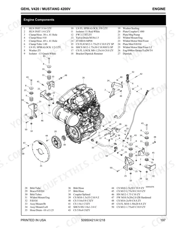
| Engine | 201-246 | Introduction, Troubleshooting Guide, Engine Components, Air Cleaner and Exhaust Components, Radiator/Cooler Components - Main, Radiator/Cooler Components - Cooler, Fuel Assembly |
Quick Reference Specifications
| Specification | Value | Page |
|---|
| Peak Torque | 480 N·m (354 ft.-lb.) @ 1600 rpm | p. 7 |
| Engine Oil Capacity (w/ filter change) | 9,5 L (10 U.S. qts.) | p. 7 |
| Engine Oil Filter Replacement Interval | 250 hours | p. 16 |
| Engine Coolant Capacity | 18,9 L (5 U.S. gal.) | p. 7 |
| Engine Horsepower - Net | 90 kW (121 hp) @ 2200 rpm | p. 7 |
| Rated Operating Capacity | 1905 kg (4200 lbs.) | p. 7 |
| Engine Oil Capacity | 9,5 L (10 U.S. qts.) | p. 7 |
| Fuel Tank Capacity | 144 L (38 U.S. gal.) | p. 7 |
| Hydraulic System Relief Pressure | 238 bar (3450 psi) | p. 7 |
| Axle Housing Locknut Torque | 280 lbf. (380 N•m) | p. 66 |
| Wheel Nut Torque | 240 lbf. (325 N•m) | p. 66 |
| Tilt Cylinder Locknut Torque | 350 ft.-lbs. (474 N•m) | p. 127 |