
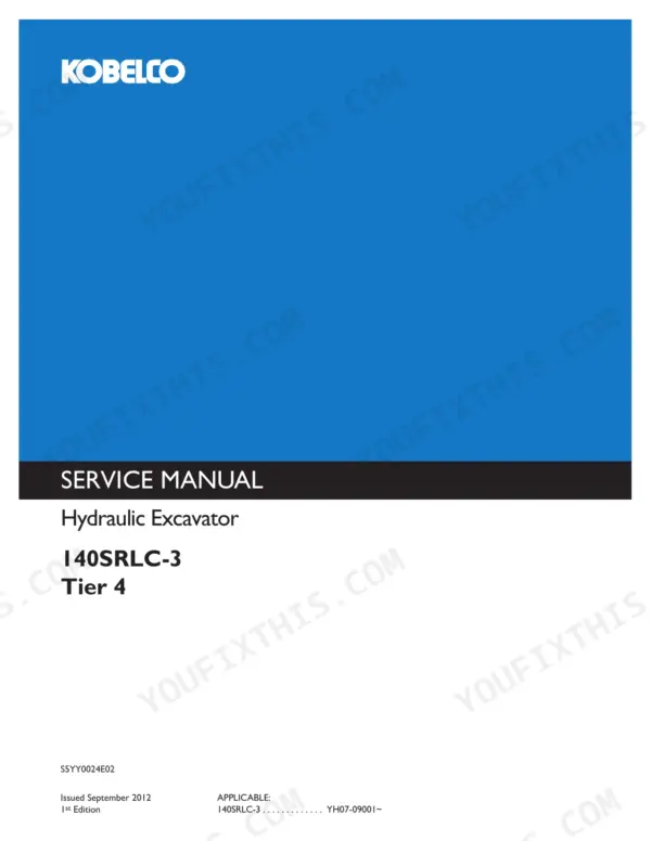
This is Kobelco Construction Machinery America's own service manual for the 140SRLC-3 Tier 4 excavator. It is Part Number S5YY0024E02, 1st Edition, issued September 2012. It covers serial YH07-09001 and up. Mitsubishi's D04EG-TAA engine manual, Pub. No. 99616-28100, is bound in at the back.
A slow boom or a lazy swing is a bad morning when the crew is standing around. This book takes you from pilot pressure to main relief to the mechatro controller. Every step has a factory number to check against, so you stop swapping parts on a hunch.
Keep it on a tablet in the service truck or a phone in the cab. The torque charts, the 10-sheet electric diagram and the error code tables go wherever the machine is parked.
What's Inside This Kobelco 140SRLC-3 Manual
| System | Pages | Key Topics |
|---|---|---|
| Cover, Index and Outline | 1-17 | Book Index, General Precautions for Making Repairs, Safety When Disassembling, Hydraulic and Electrical Equipment Handling, Weld Repair |
| Specifications and Attachment Dimensions | 18-47 | Name of Components, General Dimensions, Weight of Components, Transportation, Speed and Climbing Capability, Crawler and Bucket Types, Engine Specification (Mitsubishi D04EG-TAA), Boom/Arm/Bucket Dimensions and Maintenance Standards |
| Tools | 48-69 | Tightening Torques for Capscrews and Nuts, Hose and Fitting Torques, Plugs, Special Tools, Screw Locking Compound, Lifting Jigs, Track Spring Set Jig |
| Standard Maintenance Time Table | 70-83 | Working Conditions, Standard Working Time Table by Group, Work Codes |
| Maintenance Standard and Test Procedure | 84-115 | Performance Inspection Standard Table, Engine Speed and Hydraulic Pressure Measurement, Travel/Swing/Attachment Performance, Swing Bearing, Mechatro Controller, Exhaust Gas Post-Cleaning Device |
| Mechatro Control System | 116-191 | Unload Valve Control, Positive Control and P-Q Control, Boom Up Conflux, Arm in Recirculation and Conflux, Arm-In Anti-Cavitation, Mechatro Controller |
| Hydraulic System | 192-223 | Standard Hydraulic Circuit, N&B and Boom/Arm Safety Options, Neutral, Travel, Bucket, Boom, Swing, Arm and Combined Circuits, Pressure |
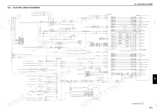
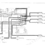
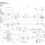
| Electric System | 224-283 | Electric Circuit Diagram (10 Sheets), Electrical Equipment, Harness List, Instrument Panel, Controller Install |
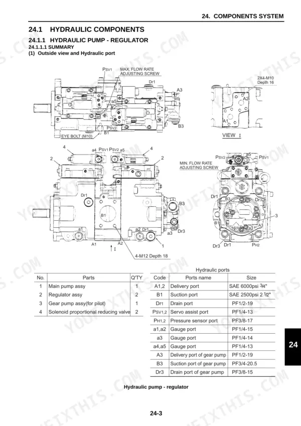
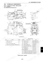
| Components System: Hydraulic Components | 284-379 | Hydraulic Pump and Regulator, Control Valve, Pilot Valves, Swing Motor Unit, Travel Motor, Swivel Joint, Cylinders |
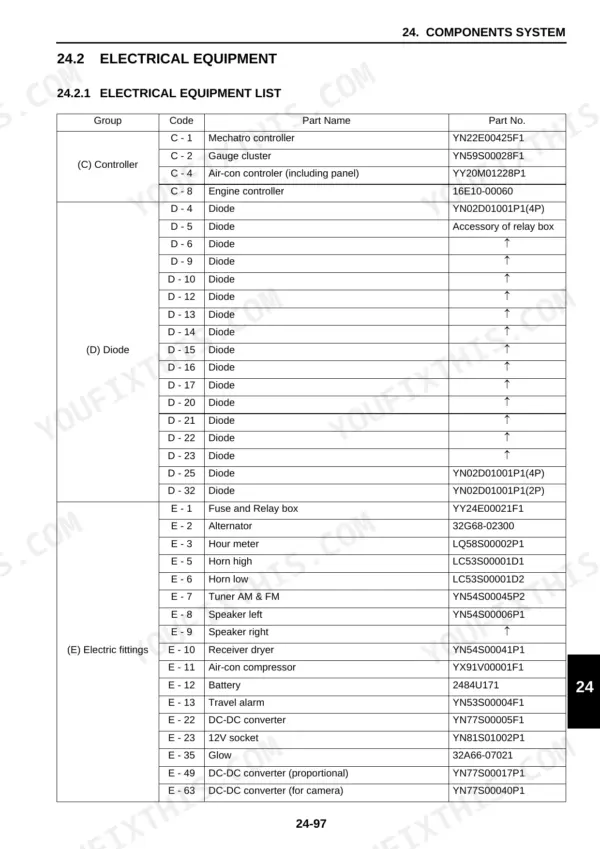
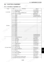
| Components System: Electrical Equipment | 380-397 | Electrical Equipment List, Electrical Equipment Specifications |
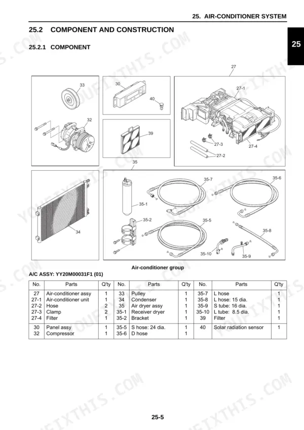
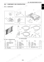
| Air-Conditioner System | 398-445 | HVAC Basic System, Components, Piping, Function, Disassembly, Charging Refrigerant, Electric Circuit, Troubleshooting |
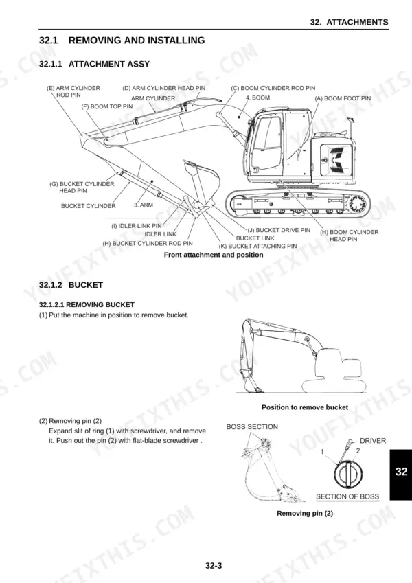
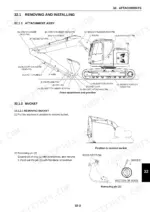
| Disassembling and Assembling: Attachments | 446-487 | Tightening Torque Indication, Attachment Assy, Bucket, Arm and Boom Removal and Installation, Disassembling and Assembling |
| Upper Slewing Structure: Removing and Installing | 488-550 | Operator Seat, Battery, Guards, Counterweight, Fuel Tank, Hydraulic Tank, Pump, Air Cleaner, Muffler, Radiator and Oil Cooler, Engine, Control Valve, Pilot Valves, Swing Motor, Swivel Joint, Upper Frame |
| Upper Slewing Structure: Disassembling and Assembling | 551-671 | Hydraulic Pump and Regulator, Control Valve, Pilot Valves (ATT and Travel), Swing Motor Unit, Swivel Joint |
| Travel System: Removing and Installing | 672-714 | Crawler, Upper and Lower Rollers, Front Idler and Adjuster, Sprocket, Travel Motor, Swing Bearing |
| Travel System: Travel Motor Unit | 715-775 | Travel Motor Construction, Tools and Jigs, Disassembly, Assembly, Maintenance Standard |
| Troubleshooting by Error Codes | 776-849 | Judgment at Site, Classification of Failure, Mechatro Controller Fuse, Error Code List and Per-Code Tables |
| Troubleshooting by Trouble | 850-895 | Hydraulic System Symptoms, Electric System Wiring Checks and Troubles, Engine Related Troubleshooting Matrix |
| Engine Manual (Mitsubishi D04EG-TAA): Preface and General | 896-921 | Engine Serial Number Plates, Engine Manual Cover and Foreword, External View, Outline of Systems |
| Engine: Service Data, Service Tools and Overhaul Instructions | 922-945 | Maintenance Service Data, Tightening Torques, Service Tools, Overhaul Instructions |
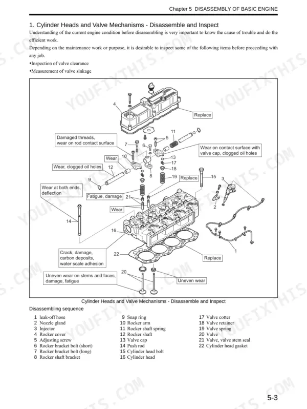
| Engine: Basic Engine Disassembly, Inspection and Assembly | 946-1015 | Disassembly, Inspection and Repair, Assembly of Basic Engine |
| Engine: Fuel, Lubrication, Cooling, Inlet/Exhaust, Electrical and Adjustment | 1016-1101 | Fuel System, Lubrication System, Cooling System, Inlet and Exhaust Systems, Electrical System, Adjustment, Break-In, Performance Test, Error Code Table |
Quick Reference Specifications
| Specification | Value | Page |
|---|---|---|
| Engine | MITSUBISHI D04EG-TAA | p. 31 |
| Total displacement | 3,331 cc (203.27 cu-in) | p. 31 |
| Rated output with fan | 74 kW (101 PS) at 2,000 min-1 | p. 31 |
| Engine oil quantity (total) | 11.5 L (2.61 gal) | p. 31 |
| Firing order | 1 - 3 - 4 - 2 | p. 31 |
| Fully equipped weight | 14,100 kg (31,090 lbs) | p. 27 |
| Travel speed (1-speed/2-speed) | 3.4 / 5.6 km/h (2.1 / 3.5 mile/h) | p. 27 |
| Swing speed | 11.0 min-1 {rpm} | p. 27 |
| H mode Hi idle / Lo idle | 2000 +30/-30 / 1100 +30/-30 min-1 | p. 87 |
| Pilot primary pressure | 5.0 (725) MPa (psi) | p. 87 |
| Main relief valve pressure (ATT) | 34.3 (4970) MPa (psi) | p. 87 |
| Over load relief pressure (boom, arm, bucket) | 37.8 (5480) MPa (psi) | p. 87 |
Kobelco 140SRLC-3 Common Problems This Manual Covers
Engine bogs down or stalls under load, or hydraulic power feels weak
Before condemning the main pump, work through the engine down/stalled table in Troubleshooting by Trouble. Use service diagnosis to read the actual current to the P1 and P2 pump proportional valves. Then measure their secondary pressure directly at ports a3 and a4. Compare against the Performance Inspection Standard Table, then go to the pump and regulator teardown in Hydraulic Components.
Manual Section: Troubleshooting by Trouble / Maintenance Standard and Test Procedure p. 855Boom up is slow even at full lever
Check the boom up pressure sensor first, using service diagnosis Operation No.3. Then put a gauge on the remote control valve. It should make 3.0 MPa or more with the boom up at full lever and high idle. If both pass, read the boom up conflux logic in Mechatro Control System and check main relief at MR1.
Manual Section: Troubleshooting by Trouble / Mechatro Control System p. 858Swing does not move or swings slowly
The swing table runs in order: swing pressure sensor, remote control valve, swing parking brake solenoid, shuttle valve, then pump pressure sensor. Swing overload relief should read 28.0 MPa (4060 psi). If the controls and pressures check out, remove and disassemble the swing motor unit following the Upper Slewing Structure chapters.
Manual Section: Troubleshooting by Trouble / Upper Slewing Structure p. 871Travel is slow or the machine pulls to one side
Read the right and left travel pressure sensors in service diagnosis, Operation No.18 and No.19. The travel remote control valve needs 2.1 MPa or more. Travel speed should be 3.4 km/h in 1st and 5.6 km/h in 2nd. If one side stays weak, pull the travel motor and check it against the maintenance standard in Travel System: Travel Motor Unit.
Manual Section: Troubleshooting by Trouble / Travel System: Travel Motor Unit p. 875Frequently Asked Questions
What does a 140SRLC-3 error code on the gauge cluster mean?
The machine runs a self-diagnosis and shows codes on the gauge cluster. Troubleshooting by Error Codes lists each code with the fault and the page that covers it. For example, B114 is a short-circuit of the optional selector positioning pressure sensor. B163 is a disconnection of the P1 side optional pressure sensor. Engine faults are listed separately in the bound-in Mitsubishi error code table, which gives P code, KCM code and J1939 SPN/FMI. p. 781
How do I clear or reset Kobelco 140SRLC-3 fault codes?
Find the cause first. A code set by a shorted sensor or a broken wire comes straight back. Stored codes sit in the mechatro controller's trouble history. Turn the starter switch on, hold the menu switch and press the buzzer stop switch 3 times, then select TROUBLE HISTORY. With that screen up, press the work mode change switch and the buzzer stop switch together for 5 seconds or more. The deletion is complete when NO ERROR shows. Every stored item is erased; the book says partial erasing is impossible. p. 173
Where are the torque specs for hydraulic fittings and hoses?
The Tools section has separate tables for capscrews and nuts, hoses and fittings, and plugs, plus screw locking compound guidance. Check whether the figure is for a dry or oiled thread. An M16 10.9T capscrew is 343±39 N•m (253±29 lbf•ft) dry but 284±29 N•m (209±21 lbf•ft) oiled. Component torques, like the N&B cartridge relief valve body at 68.5~78.5 N-m, are in the teardown chapters. p. 51
What torque do the 140SRLC-3 sprocket and travel motor capscrews get?
The sprocket is held by 18 M16x45 capscrews. Coat them with Loctite #262, set the machine back on the ground, then tighten to 279 N-m (206 lbf-ft) with a 24 mm socket. The travel motor M16 capscrews take the same 279 N-m (206 lbf-ft) with Loctite #262, and its M12 SEMS bolts take 83.4 N-m (61 lbf-ft). For other hardware, match size and grade to the capscrew chart in Tools. p. 705
What should main relief and pilot pressure read on a healthy 140SRLC-3?
Main relief is 34.3 MPa (4970 psi), adjusted at MR1 and read with the boom up over relief. Pilot primary is 5.0 MPa (725 psi) at G pump port a4, at high idle. Boom, arm and bucket overload reliefs are 37.8 MPa (5480 psi). Bring the oil to 50 °C (122 °F) at the tank surface first, or your readings will mislead you. p. 87

Reviews
There are no reviews yet.