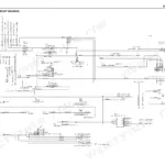
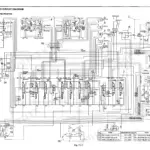
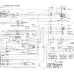
Relief valve settings, track tension and swing reduction service for the Kobelco SK150LC III hydraulic excavator are settled in one 770-page shop manual, Kobelco publication S5YM0001E-00. As a Kobelco SK150LC III shop manual PDF, it pairs a hydraulic system diagram tracing the neutral, travel, swing and bucket circuits with wiring diagrams for the electrical system. Troubleshooting runs system by system. Drive, hydraulic, swing, travel, attachment, control and electrical faults each get their own section, and the travel chapter works through track links, upper and lower rollers, the idler and the track tension assembly. Set travel main relief to 350-385 kg/cm² (4980-5050 psi), then confirm primary pilot pressure at 47-53 kg/cm² (670-754 psi). When your fault sits in the travel circuit, the hydraulic diagram shows how that circuit is routed. Bookmarked by system and searchable as text, the PDF lets you finish that relief check to Kobelco's own figures.
What's Inside This Manual
| System | Pages | Key Topics |
|---|
| Operation and Controls | 2-7 | |
| Preventive Maintenance | 8-9 | |
| Specification | 10-25 | Location of Components, General Dimensions, Specifications and Performance |
| Location and Weight of Components | 26-31 | Weight of Components, Transportation Weight |
| Maintenance Standards and Test Procedures | 32-77 | Performance Inspection Standard |
| Troubleshooting | 78-103 | Drive System, Hydraulic System, Swing System, Travel System, Attachment System, Control System, Electrical System |
| Tightening Torques for Fasteners | 104-107 | Capscrews, Nuts, Sleeves, Special Spanner, Screw Locking Compounds |
| Troubleshooting and Maintenance Standards | 108-109 | Application Table, Maintenance Standards, General Repair Instructions |
| Systems Overview | 110-111 | |
| Drive System | 112-125 | Power Plant, Hydraulic Pump, Coupling, Radiator, Suction Stopper |
| Hydraulic System | 126-147 | Hydraulic System Diagram, Neutral Circuit, Travel Circuit, Swing Circuit, Bucket Circuit |
| Swing System | 148-168 | Slewing Ring, Swing Control Valve, Swing Motor Assembly, Swing Reduction Unit |
| Travel System | 169-219 | Lower Machinery, Track Link, Upper Roller, Lower Roller, Idler, Track Tension Assembly |
| Attachments | 220-237 | Attachment System, Removal and Installation of Attachment |
| Engine Control Installation | 238-249 | Travel and Operate Control System, Work Control System |
| Upper Frame | 250-261 | Hydraulic Oil Tank, Fuel Tank, Removal and Installation of Cab |
| Electrical System | 262-269 | Location of Electrical Components, Wiring Harnesses |
| Fresh Air Heater | 270-275 | Construction of Main Components, Operating Principle |
| Engine | 276-486 | Lubricating System, Fuel System, Turbocharger |
| Shop Manual Components | 487-585 | Hydraulic Pump, Regulator, Pilot Valve |
| Control Valve | 586-770 | Holding Valve, Hydraulic Cylinder |
Quick Reference Specifications
| Specification | Value | Page |
|---|
| Primary pilot pressure | 47-53 kg/cm² (670-754 psi) | p. 35 |
| Travel main relief pressure | 350-385 kg/cm² (4980-5050 psi) | p. 35 |
| Upper Limit Pressure (Variable loading mode switch) | 16.0 ± 1.0 kg/cm² (227 ± 14 psi) | p. 54 |
| Lower Limit Pressure (Variable loading mode switch) | 11.0 ± 1.0 kg/cm² (156 ± 14 psi) | p. 54 |
| Tightening torque for shoe bolt | 95 ± 2 kgf·m (687 ± 14.5 ft-lbs) | p. 213 |
| Tightening torque for filter assy (2-1) | 7-8 kgf·m (51-58 ft-lbs) | p. 645 |
| Tightening torque for check valve assy (3-7) | 4.8-5.5 kgf·m (35-40 ft-lbs) | p. 645 |
| Torque for capscrews on slewing ring | First 15 kgf-m (108 ft-lbs), Second 57.5 ± 5.5 kgf-m (415 ± 40 ft-lbs) | p. 168 |
| For reduction unit mounting capscrews | 28.5 ± 3 kgf·m (206 ± 22 ft-lbs) | p. 211 |
| For sprocket mounting capscrews | 28.5 ± 3 kgf·m (206 ± 22 ft-lbs) | p. 211 |
| Swing speed | 11.4 rpm | p. 15 |
| Engine rated output | 100 ps / 2,300 rpm | p. 15 |