| Specifications | 7-21 | Name of Components, Specifications and Performance, Type of Bucket, Combination of Attachments, Working Range, Lifting Diagram, Engine Specifications |
| Location and Weight of Components | 22-27 | Location of Components, Unit Weight, Transportation Weight and Dimensions |
| Maintenance Standard and Test Procedure | 28-32 | Pilot Circuit Pressure, Main Circuit Pressure, Travel Performance, Slewing Performance, Attachment Operability, Slewing Bearing Wear |
| Operation | 33-44 | Pressure Measurement and Adjustment, Measurement of Travel Performance, Measurement of Slewing Performance |
| Work Standard | 45-50 | Tightening Torques for Capscrews and Nuts, Tightening Torques for Nuts and Sleeves, Screw Size and Tightening Tool Size |
| Systems Section Overview | 51-52 | |
| Drive System | 53-65 | Power Plant, Hydraulic Pump Removal, Coupling Installation, Radiator Installation, Engine Removal, Suction Stopper |
| Hydraulic System | 66-101 | Hydraulic Circuit Diagrams, Neutral Circuit, Travel Circuit, Slewing Circuit, Bucket Circuit, Boom Circuit |
| Steering System | 102-109 | Steering Valve, Steering Cylinder, Handle Assembly, Toe-In Adjustment, Steering Angle Adjustment |
| Travel System | 110-128 | Front Axle, Rear Axle, Transmission, Equalizer, Tire Specifications, Travel System Hydraulic Lines |
| Brake Control System | 129-140 | Wheel Brake, Parking Brake, Brake Valve, Selector Valve, Brake Oil Reservoir, Air Bleeding |
| Attachment | 141-157 | Operation of Attachment System, Attachment Pilot System, Dynamic Damper (DD) Circuit, Removal and Installation of Attachment, Maintenance Standard |
| Control System | 158-210 | Operator Control, Mechatro Control, Engine Control, Major Electrical Equipment |
| Upper Frame | 211-220 | Construction of Upper Frame, Hydraulic Tank, Removal and Installation of Counterweight, Removal and Installation of Cab, Maintenance Standard |
| Pneumatic System | 221-239 | Pneumatic System and Switch Operation, Pneumatic System Line, Outline of Pneumatic Equipment |
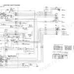
| Electrical System | 240-259 | Boom Working Light Harness, Engine Harness, Upper Harness, Steering Assy, Controller Assy |
| Air Conditioning System | 260-297 | Construction of Major Equipment, Disassembling and Assembling, Refrigerant Charging Method, Electric Circuit, Troubleshooting |
| Pump | 298-340 | Construction and Operation, Disassembly and Assembly, Regulator, Pump Control Curve, Hydraulic Gear Pump |
| Steering Valve | 341-445 | Pilot Relief Valve, Pilot Valve, Control Valve, Construction and Operation, Disassembly and Assembly, Troubleshooting and Measures to Be Taken, Pilot Check Valve |
| Hydraulic Motor | 446-503 | Swivel Joint, Construction and Operation, Disassembly and Assembly, Counter Balance Valve (Brake Valve), Anticavitation Valve, Maintenance Standard, Troubleshooting and Measure to Be Taken |
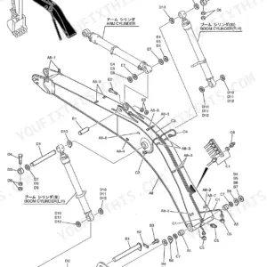
| Hydraulic Cylinder | 504-550 | Construction and Operation, Disassembly and Assembly, Maintenance Standard, Jig and Tools, Dozer Cylinder (Option) |
| Reduction Unit | 551-594 | Transmission, Construction and Function, Disassembly and Assembly, Maintenance Standards, Construction and Operation, Maintenance Standard, Troubleshooting and Measures to Be Taken |
| Rear Axle | 595-664 | Carrier Assy, Planetary Gearing and Hub Assy, Front Axle, Disk Brake Assy, Maintenance Standard |
| Engine | 665-855 | Group 12 Lubrication, Group 13 Fuel and Engine Control, Group 54 Electrical System |