

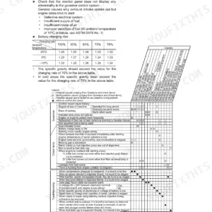
Four electric lift trucks in Komatsu's FBM and FB line, from the FBM10M through the FB18M-2, share this 72-page Komatsu FB15M service manual PDF, factory document SM019. Troubleshooting flowcharts fill nearly a third of the book, tracing a dead FR contactor, a truck that won't move in either direction, or travel speed that ignores the accelerator back to the failed component. Wiring diagrams for the 24V USA, 24V and 48V pump controller, and pump contactor configurations close it out, and the chopper circuit gets its operating theory explained mode by mode, so you can read a thyristor check instead of guessing at one. Gap the 48V FR contactor microswitch at 0.5 to 0.7 mm; set LIFT first-stage lever travel to 15 to 25 mm at the cam. Meanwhile the truck sits and pallets pile up. Print what you need and let it get greasy; the bookmarked, keyword-searchable file stays clean on your drive.
Complete the set for your FBM10M-2, FBM13M-2, FB15M-2…
- Operator Manual: Komatsu FB10M-2 to FB18M-2 Operator Manual
What's Inside This Komatsu FBM10M-2, FBM13M-2, FB15M-2, FB18M-2 Manual
| System | Pages | Key Topics |
|---|---|---|
| Electrical System Overview | 2-3 | Stop Lamp Sw, Power Steering Motor, Chopper Panel, Motor, Service Data, Brush Height |
| Switch and Contactor Adjustment | 4-5 | Control Valve Lever Cam Adjustment, Parking Brake, Lever Travel From Neutral, Tire Swing Switch, Contactor Fr Contactor Bypass Contactor, Contactor Microswitch Clearance |
| Controller System and Control Circuit | 6-9 | Mounting Position and Outline of Controller, Outline, Safety Circuits, Schematic Control Circuit, Symbol and Name Table, Fr Contactor, Accelerator, Travel Contactor Switch Circuit |
| Chopper and Contactor Panel Components | 10-15 | Contactor Panel, Diode Plugging and Flywheel, Plugging, Fr Contactor, Bypass Contactor, Chopper Circuit, Chopper Panel, 48V Type |
| Chopper Circuit Operation | 16-20 | Principle of Changing Speed in Travel Motor, Average Motor Voltage, Chopper System, Mode 1, Mode 2, Mode 3, Mode 4, Mode 5 |
| Inspection and Adjustment | 21-22 | Function and Adjustment of Controller Circuit, Current Limit Circuit, Overheat Prevention Circuit, Plugging, Runaway Prevention Circuit, Pcs, Turning Control |
| Main Electrical Parts Inspection | 23-45 | Inspection Tool and Measurement Device, Tightening Torque, Voltage Check, Print Card, Thyristor Check, Diode, Resistance, Condenser |
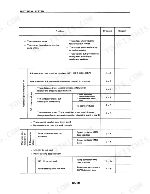
| Troubleshooting | 46-68 | Before Starting Troubleshooting, Methods of Using Flowchart, Explanation of Terms Used in Troubleshooting Flowchart, Precautions When Troubleshooting, Problem Symptom Table |
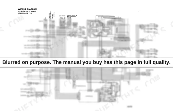
| Wiring Diagrams | 69-72 | 24V Usa Type, 24V Hydraulic Pump Controller Type, 48V Hydraulic Pump Controller Type, 24/48V Pump Contactor Type |
Quick Reference Specifications
| Specification | Value | Page |
|---|---|---|
| Contactor microswitch clearance (24V FR contactor, 24V/48V Bypass contactor) | 30 - 50% of stroke | p. 5 |
| Contactor microswitch clearance (48V FR contactor) | 0.5 - 0.7 mm | p. 30 |
| Control valve lever cam adjustment (Lift 1st lever travel) | 15 - 25 mm | p. 4 |
| Control valve lever cam adjustment (Lift 2nd lever travel) | 55 - 65 mm | p. 4 |
| Voltage check at CN1 (10) | approx. 13 V | p. 51 |
| Drive motor rated output (24V) | 2.4 kW | p. 3 |
| Pump motor rated output (48V) | 6.6 kW | p. 3 |
| Pump motor rated output (24V) | 6.5 kW | p. 3 |
| Power steering motor rated output | 0.45 kW | p. 3 |
| Drive motor commutator diameter repair limit (24V) | 77 mm | p. 3 |
| Drive fuse capacity (24V) | 350 A | p. 10 |
Komatsu FBM10M-2, FBM13M-2, FB15M-2, FB18M-2 Common Problems This Manual Covers
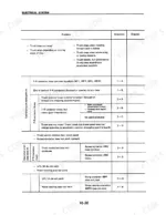
Komatsu FB15M electric forklift will not travel in either direction, no chopping sound from chopper panel
Check the drive fuse on the chopper and contactor panel: 350 A on 24V trucks, 225 A on 48V trucks (page 10). If the fuse checks good, follow the no-travel flowchart in the troubleshooting section starting on page 46, and listen for chopping sound with the accelerator pressed before condemning the print card.
Manual Section: Travel System TroubleshootingF-R contactor will not close, truck powers up but stays dead in forward and reverse
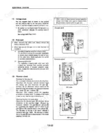
Check seat switch and direction lever inputs first, then measure voltage at CN1 terminal (10); expect approximately 13 V (page 51). If voltage is present, inspect the contactor microswitch clearance: 0.5 to 0.7 mm on 48V FR contactors (page 30). Replace the microswitch if the tips are burned or clearance will not hold adjustment.
Manual Section: F-R Contactor Troubleshooting p. 48Travel speed stays constant regardless of accelerator pedal position, top speed only or crawl only
Test the accelerator circuit at CN1 terminal (9); a healthy signal reads approximately 13 V (page 51). If voltage checks good, inspect the accelerator potentiometer and its linkage, then check the thyristor and condenser using the inspection procedures starting on page 24. Replace the print card only after the input side tests clean.
Manual Section: Travel Speed TroubleshootingTruck travels but will not reach full speed, bypass contactor never closes
Adjust the bypass contactor microswitch clearance to 30 to 50 percent of switch stroke (page 5), then confirm the contactor tips close fully by hand. Check coil voltage against the wiring diagram on page 69 for your voltage type. Clean or replace burned tips; a dragging armature keeps the truck stuck in chopper mode.
Manual Section: Bypass Contactor TroubleshootingPower steering contactor will not close and steering goes heavy at low speed
Check the power steering fuse first: 100 A on 24V trucks, 40 A on 48V trucks (page 10). Test the MPS coil circuit against the wiring diagram on page 69. If the contactor closes but the 0.45 kW steering motor stays dead (page 3), inspect the motor brushes and commutator before replacing the contactor.
Manual Section: Power Steering Contactor TroubleshootingFrequently Asked Questions
What are the torque specifications for the main electrical components on the Komatsu FBM10M, FBM13M-2, FB15M, FB18M-2?
The tightening torque for the main thyristor (SM) heat sink mounting portion is 270 kg-cm (20 lb-ft or 26 Nm). For the thyristor (SS) heat sink mounting portion, it is 65 kg-cm (4.7 lb-ft or 6.4 Nm). p. 23
What is the standard brush height for the drive motor?
The standard brush height for the drive motor is 33 mm (1.3 in). The repair limit for the brush height is 22 mm (0.87 in). p. 3
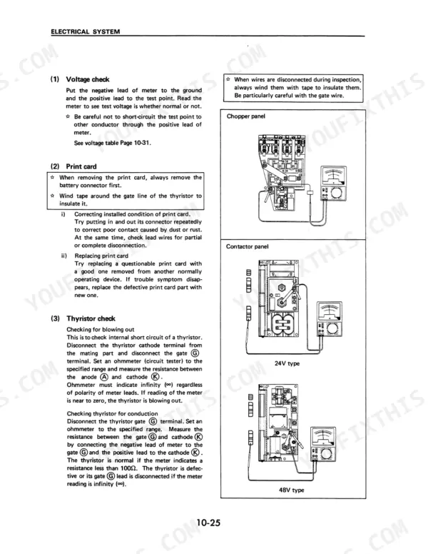
What is the procedure for checking the thyristor for conduction?
Disconnect the thyristor gate terminal and set an ohmmeter to the specified range. Measure the resistance between the gate and cathode by connecting the negative lead to the gate and the positive lead to the cathode; the system is normal if the resistance is less than 100 ohms. p. 24
What is the drive fuse capacity for the 48V system on a Komatsu FBM10M, FBM13M-2, FB15M, FB18M-2 forklift?
For a 48V system, the drive fuse capacity is 225 A. For a 24V system, the capacity is 350 A. p. 10
What is the function of the thermosensor on the controller?
The thermosensor detects the temperature of the aluminum block to which the main thyristor is fitted. If the temperature exceeds 90°C, the actuator reduces the voltage of the accelerator to decrease travel speed and prevent further temperature rise. p. 14
Do I get instant access to this Komatsu FBM10M Service Manual?
Immediate download of the complete 72-page searchable Service Manual. Access it on any device, from a laptop at your desk to a phone in the field.
Can I print pages of this Komatsu FBM10M manual for my own shop?
Yes. Print a single page or a chapter for your own shop use, on letter or A4.

Reviews
There are no reviews yet.