
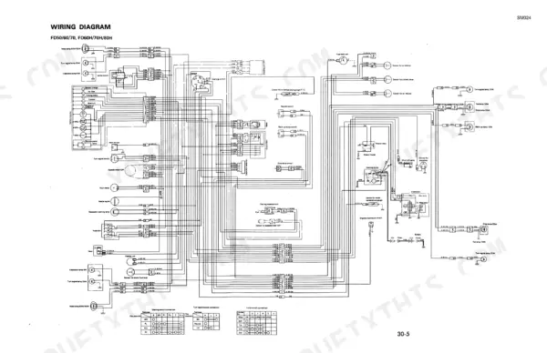
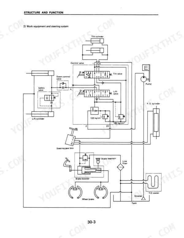
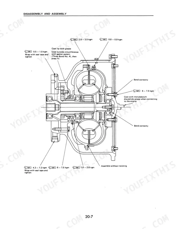
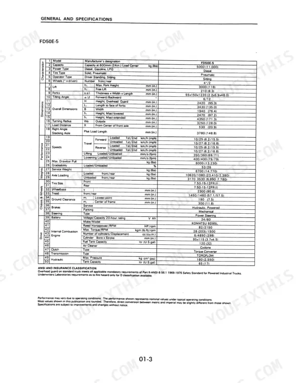
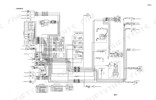
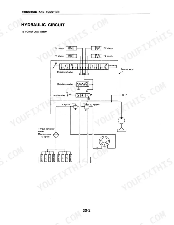
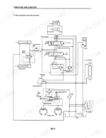
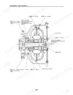
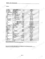
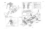
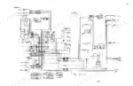
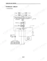
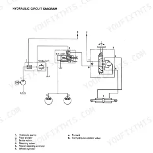
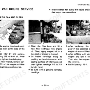
Torque converter, transmission, steering gear box, hydraulic circuit and brake system are taken apart and explained in this 179-page Komatsu FG50-5, FG60-5, FG70-5 and FD50-5 through FD80H-5 shop manual PDF (SM024), written for twelve FG and FD forklift truck variants. Wiring diagrams trace the truck's electrical circuits, while the hydraulic schematics show oil routing from the pump through the control valve to the lift and tilt cylinders. Disassembly and assembly fills the largest share of the book, with torque tables set inside the procedures, and the maintenance guide lays out your periodic service table. Set the work equipment circuit to 180 kg/cm², and fill the differential to 11.5 L, or 13.5 L on the FD60H-5, FD70H-5 and FD80H-5. A guessed relief pressure under a raised load is dangerous. Bookmarked by section and text-searchable, your copy finds the right figure fast and has the truck lifting again by the next shift.
What's Inside This Komatsu FG50-5 to FD80H-5 Series Manual
| System | Pages | Key Topics |
|---|---|---|
| General and Specifications | 7-26 | Overall Dimensions and Specifications |
| Removal and Installation | 27-45 | General Locations |
| Torque Converter | 48-53 | |
| Transmission | 54-87 | |
| Steering Gear Box | 88-117 | |
| Structure and Function | 118-140 | Hydraulic Circuit, Brake System |
| Maintenance and Inspection Guide | 141-168 | Periodic Maintenance, Maintenance Table |
| Conversion Table | 169-179 | Length Conversion, Volume Conversion, Mass Conversion, Pressure Conversion, Torque Conversion, Temperature Conversion |
Quick Reference Specifications
| Specification | Value | Page |
|---|---|---|
| All Models | ||
| Differential oil capacity | 11.5 L | p. 159 |
| Differential oil capacity (FD60H/70H/80H) | 13.5 L | p. 159 |
| Work equipment circuit hydraulic pressure | 180 kg/cm² | p. 112 |
| Steering wheel play | 5 mm (Engine stopped), 20-30 mm (Engine idling) | p. 146 |
| FD50E-5 | ||
| FD50E-5 Engine Oil Capacity | 120 L | p. 9 |
| FD60E-5 | ||
| FD60E-5 Engine Oil Capacity | 120 L | p. 11 |
| FD70E-5 | ||
| FD70E-5 Engine Oil Capacity | 120 L | p. 13 |
| FG50-5 | ||
| FG50-5 Fuel Tank Capacity | 120 L | p. 15 |
| FD50-5 | ||
| FD50-5 Fuel Tank Capacity | 120 L | p. 15 |
| FD60H-5 | ||
| FD60H-5 Fuel Tank Capacity | 120 L | p. 21 |
| FD70H-5 | ||
| FD70H-5 Fuel Tank Capacity | 120 L | p. 23 |
| FD80H-5 | ||
| FD80H-5 Fuel Tank Capacity | 120 L | p. 25 |
Komatsu FG50-5 to FD80H-5 Series Common Problems This Manual Covers
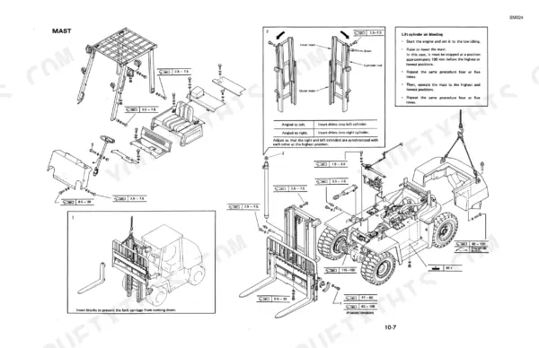
Komatsu FD70-5 mast lift cylinders out of sync, mast angled left or right at full height
Check cylinder sync after bleeding air: start the engine at low idle, then raise and lower the mast four or five times, stopping about 100 mm short of top and bottom, and cycle full stroke four or five more times (page 33). Keep clear of moving parts (page 42). If the mast leans left at full height, shim the left cylinder; leaning right, shim the right. On FD60H/70H/80H, block the fork carriage against dropping.
Manual Section: Lift cylinder air bleeding p. 33Wheel brake system holding air after line work, air bubbles discharging at the air vent valve
Remove the air vent plug and fit a vinyl hose, keeping its free end in a container of brake oil (page 37). Loosen the vent valve about 3/4 turn and press the pedal fully, repeating until the hose shows no more air bubbles. Tighten the valve and cap it. On FD60H/70H/80H, bleed the lower cylinder first. Adjust pedal play with the booster push rod.
Manual Section: Brake system air bleeding p. 37Wheel brake linings worn thin and brake drum inside diameter worn past repair limit
Measure lining thickness on FD50/60/70 and FD50E/60E/70E against the 10 mm standard and replace shoes at 5.2 mm, following page 80. Measure brake drum inside diameter: standard is 317.5 mm, replace at 320.5 mm (page 78). Check wheel cylinder piston clearance, replacing at 0.15 mm or when cracks, chips or internal rust show.
Manual Section: Wheel brake inspection p. 80Lift cylinder piston rod scored deep enough to catch a fingernail, bushing worn to red copper
Remove pressure before teardown: lower the forks to the ground, stop the engine and move each control lever two or three times (page 39). Measure piston rod to bushing clearance against 0.05 to 0.25 mm and replace at 0.4 mm, following page 107. Replace the rod if scratches catch a fingernail or wear exceeds 0.15 mm; replace the bushing when red copper shows over a quarter of its circumference.
Manual Section: Lift cylinder inspection p. 107Steering wheel play excessive with king pin and center pin worn on the steer axle
Measure steering wheel play: 5 mm with the engine stopped and 20 to 30 mm at idle (page 146); stay clear of moving parts while it runs (page 42). Then inspect the steer axle following page 74. On FD50/60/70 and FD50E/60E/70E, replace a king pin worn below 39.8 mm or a center pin below 59.5 mm, and shim knuckle vertical play past 0.2 mm.
Manual Section: Steering axle inspection p. 74Transmission clutch actuating pressure out of spec, drive and driven clutch plates worn thin
Test clutch actuating pressure against 9.6 to 18.5 kg/cm² (page 130), keeping clear of moving parts while the engine runs (page 42). With the clutch pack apart, measure plate thickness following page 60: replace drive plates below 1.1 mm, driven plates below 2.8 mm, or any plate with oil groove depth under 0.05 mm. Fill transmission oil to 12 L.
Manual Section: Transmission control valve inspection p. 60Frequently Asked Questions
What are the torque specifications for Komatsu FD50-5, FD60-5, and FD70-5?
The manual provides a standard tightening torque table for bolts on page 5. For example, using a torque wrench, an M12 bolt (ISO threads) has a target torque of 11.5 kg.m, while an M20 bolt has a target of 56 kg.m. p. 5
What replacement engine, hydraulic, transmission oil and axle lube specs fit the Komatsu FG50-5 to FD80H-5 Series?
The lubrication chart on page 166 specifies the following: Engine oil (Diesel) is SAE 10W-CD or SEA 30W-CD, Hydraulic oil is SAE 10W-CD, Gear oil for the differential is SAE 90-GL4, and transmission oil is SAE 10W-CD. p. 166
What is the correct engine oil capacity for the Komatsu FD50E-5?
The engine oil capacity for the FD50E-5 is 120 liters (32 U.S. gal) for the fuel tank, but the engine oil capacity is not explicitly listed in the table on page 9. However, the fuel tank capacity is 120 liters. p. 9
What is the procedure for bleeding the lift cylinder air?
To bleed the lift cylinder, start the engine at low idling, raise or lower the mast, and stop approximately 100 mm before the highest or lowest positions. Repeat this procedure four or five times as described on page 33. p. 33
What is the standard valve clearance for the FD60H/70H/80H engine on the Komatsu FG50-5 to FD80H-5 Series?
For the FD60H/70H/80H engine, the intake valve clearance is 0.35 mm and the exhaust valve clearance is 0.50 mm when the engine is cold. p. 153
What do I get after purchasing this Komatsu FG50-5 manual?
Straight to your device: 179 pages of searchable Shop Manual, downloadable the moment payment goes through.
Am I free to print this Komatsu FG50-5 Shop Manual?
Yes. It prints from any PDF reader, so run off the pages you need for your own repair work.
Reviews
There are no reviews yet.