
Within the hour you could have this Komatsu PC78US-6, PC78UU-6 shop manual PDF open beside the machine, checking bucket pin wear against factory limits: 785 pages of service data issued under OEM ID SEBM025109 covering both hydraulic excavator variants. Troubleshooting takes up the largest share of the book, organized by Komatsu's own diagnostic modes, from governor and pump control faults to travel deviation and hydraulic drift, each traced to a cause. Full hydraulic and electrical circuit diagrams sit at the back, and the disassembly section walks the main pump, cylinder head, and counterweight off and back on. Check arm and bucket pin-to-bushing clearance against the 0.105 to 0.233 mm limit, then torque the track frame idler cushion bolts to 186 to 225 Nm. A guessed pressure figure can cost you a rebuilt pump. Bookmarked and text-indexed, this PDF puts the H-mode drift chart two clicks away.
What's Inside This Komatsu PC78US-6, PC78UU-6 Manual
| System | Pages | Key Topics |
|---|---|---|
| General | 27-47 | Specification Dimensions Drawing, Specifications, Weight Table |
| Structure and Function, Maintenance Standard | 48-275 | Power Train System, Swing Circle, Swing Machinery, Track Frame and Idler Cushion |
| Standard Value Tables | 276-293 | Engine Standard Values, Chassis Standard Values, Electrical Parts Standard Values |
| Testing and Adjusting Procedures | 294-335 | Engine Speed Measurement, Exhaust Gas Color, Valve Clearance, Compression Pressure, Fuel Injection Timing, Track Shoe Tension |
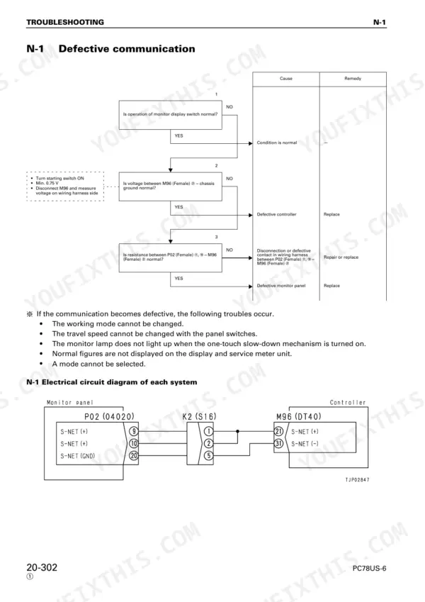
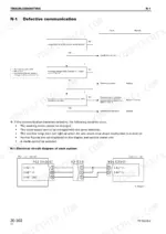
| Troubleshooting - General and Communication | 336-417 | Troubleshooting Sequence, Connector Handling, Communication System (N Mode) |
| Troubleshooting - Controller (Governor and Pump Control) | 418-502 | Governor Control System (E Mode), Pump Control System (C Mode), Engine Start/Stop Issues |
| Troubleshooting - Input Signal System (F Mode) | 503-511 | Swing Pressure Switch, Travel Pressure Switch, Boom Raise Pressure Switch, Arm in Pressure Switch |
| Troubleshooting - Hydraulic and Mechanical Systems (H Mode) | 512-577 | Work Equipment Speed/Power, Swing Speed/Power, Travel Deviation, Hydraulic Drift |
| Troubleshooting - Machine Monitor System (M Mode) | 578-608 | Monitor Panel Display, Wiper System, Washer Motor, Fuel Level Sensor, Coolant Temperature Sensor |
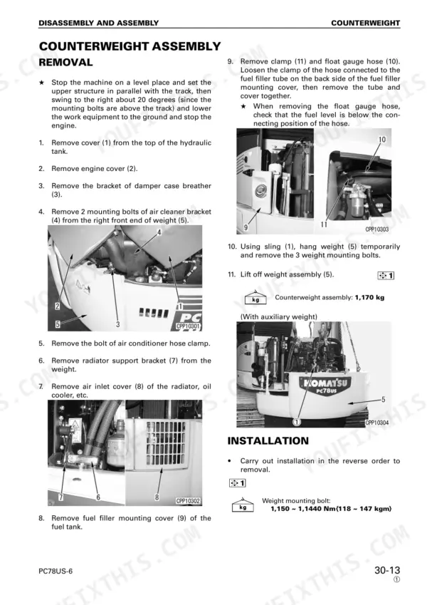
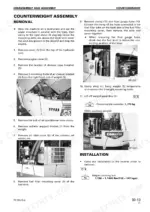
| Disassembly and Assembly | 609-689 | Counterweight Assembly, Injection Pump Assembly, Cylinder Head Assembly, Main Pump Assembly |
| Other Specifications (PC78US-6 for Norway) | 690-767 | Norway Specification Dimensions Drawing, Norway Specifications, Norway Weight Table |
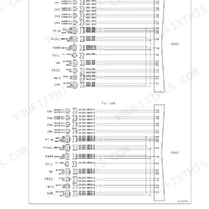
| Others | 768-785 | Hydraulic Circuit Diagram, Electrical Circuit Diagram |
Quick Reference Specifications
| Specification | Value | Page |
|---|---|---|
| Torque for track frame and idler cushion bolts | 186 - 225 Nm | p. 56 |
| Hydraulic pump bolt torque (PEN, PDA, PM, PD) | 7.8 - 9.8 Nm | p. 95 |
| Hydraulic pump bolt torque (Ppls, P1T, P1) | 11.8 - 19.6 Nm | p. 95 |
| Clearance between mounting pin and bushing of arm and bucket | 0.105–0.233 mm | p. 201 |
| Clearance between mounting pin and bushing of bucket and link | 0.131–0.245 mm | p. 201 |
| Clearance between mounting pin and bushing of boom and arm | 0.130–0.274 mm | p. 201 |
| Clearance between 1st boom and 2nd boom mounting pin and bushing | 0.156–0.297 mm | p. 205 |
| Ball joint (2) to solenoid (1) thread clearance | Approx. 1mm | p. 308 |
| Screwing depth b of rod in ball joint | Approx. 12.5 mm | p. 308 |
| Travel speed selector solenoid output pressure (ON) | 3.14 ± 0.49 MPa | p. 322 |
| Swing machinery case mounting bolt | 245 ~ 308.7 Nm | p. 642 |
| Ring gear mounting bolt | 58.5 ~ 73.5 Nm | p. 647 |
Komatsu PC78US-6, PC78UU-6 Common Problems This Manual Covers
Komatsu PC78US-6 engine lugs down under load, bucket won't curl with force while digging
Test main relief pressure at the pump; spec is 26.5 MPa per page 146. If it comes up low, adjust the relief valve or suspect pump wear. Follow the H Mode charts for weak work equipment speed and power starting on page 512, and verify the pilot circuit holds 3.1 MPa control relief pressure (page 92).
Manual Section: Troubleshooting for Hydraulic and Mechanical Systems (H Mode) p. 512Engine starts then dies after a few seconds, or shuts down intermittently during operation
Check the fuel pump solenoid linkage before condemning parts. Verify stop lever end play of 1.0 to 2.0 mm per page 207, and confirm roughly 1 mm of thread clearance between the ball joint and solenoid during adjustment on page 308. Then run the E Mode engine start and stop troubleshooting beginning on page 418.
Manual Section: Troubleshooting for Controller (Governor Control System) (E Mode) p. 418Second travel speed does not engage, monitor shows error code E206 or E216
Test the travel speed selector solenoid output with a pressure gauge; it should read 3.14 plus or minus 0.49 MPa when energized, per the procedure on page 322. If pressure is low, check the solenoid coil and harness for opens or shorts, then follow the C Mode charts for the travel speed selection system.
Manual Section: Troubleshooting for Controller (Pump Control System) (C Mode)Bucket rattles on the arm pin, sloppy feel at the teeth when digging
Measure pin to bushing clearance with the bucket blocked and unloaded. On the PC78US-6, standard clearance between the arm and bucket mounting pin and bushing is 0.105 to 0.233 mm; check your readings against the maintenance standards on page 201. Replace pins and bushings past the limit, then shim end play out of the joint.
Manual Section: Structure and Function, Maintenance Standard p. 201Track chain sags and jumps the idler, tension will not hold during travel
Check track shoe tension per the adjusting procedure starting on page 294 and grease the adjuster until sag is correct. Inspect the idler cushion for wear or leakage; if the cushion mounting has loosened, torque the track frame and idler cushion bolts to 186 to 225 Nm as specified on page 56.
Manual Section: Testing and Adjusting Procedures p. 294Frequently Asked Questions
How do I reset an error code on the Komatsu PC78US-6?
To delete saved service codes, press the 'Buzzer cancel switch (8)' and turn the starting switch OFF simultaneously, then turn the starting switch ON again and push and hold the 'Buzzer cancel switch (8)' for 5 seconds. p. 400
What is the torque specification for the swing machinery case mounting bolts on the Komatsu PC78US-6, PC78UU-6?
The swing machinery case mounting bolts should be tightened to a torque of 245 to 308.7 Nm (180.7 to 227.7 lb-ft). p. 642
What is the capacity of the hydraulic tank for the PC78US-6?
The hydraulic tank capacity for the PC78US-6 is 64 liters (16.9 US gallons). p. 657
What is the standard valve clearance for the Komatsu PC78US-6, PC78UU-6 engine?
The standard valve clearance for the air intake valve is 0.35 mm and for the exhaust valve is 0.50 mm. p. 277
What is the tightening torque for the cylinder head mounting bolts on the Komatsu PC78US-6, PC78UU-6?
The cylinder head mounting bolts should be tightened in a specific order to 107.8 ± 4.9 Nm (79.5 ± 3.6 lb-ft) and then tightened an additional 90 degrees. p. 628
What format is this Komatsu PC78US-6 manual in?
A single searchable PDF file of 785 pages, downloadable right after payment. Nothing ships, nothing waits in the mail.
Does this Komatsu PC78US-6 manual allow printing?
Yes. It prints from any PDF reader, so run off the pages you need for your own repair work.



Reviews
There are no reviews yet.