
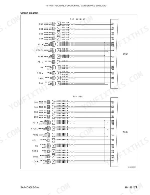
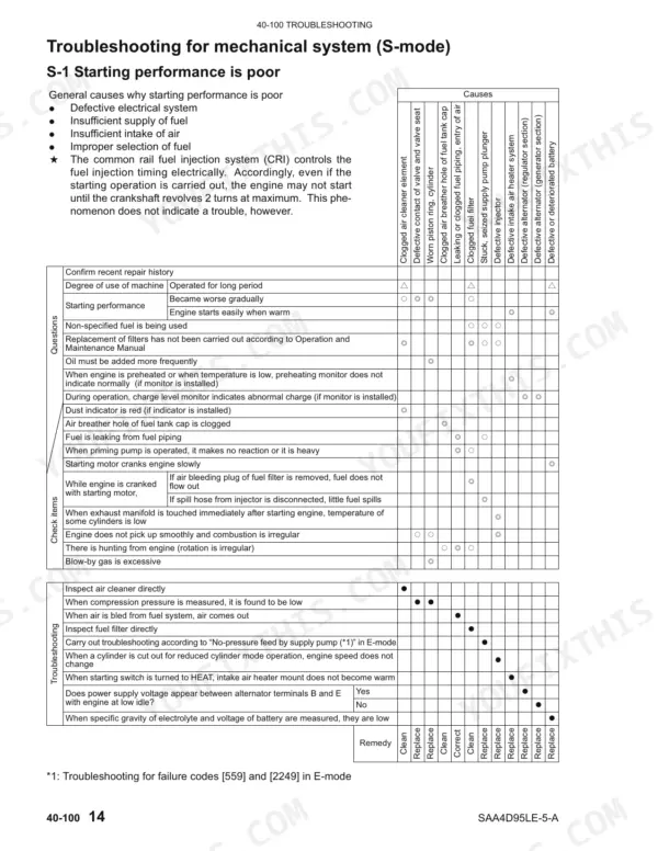
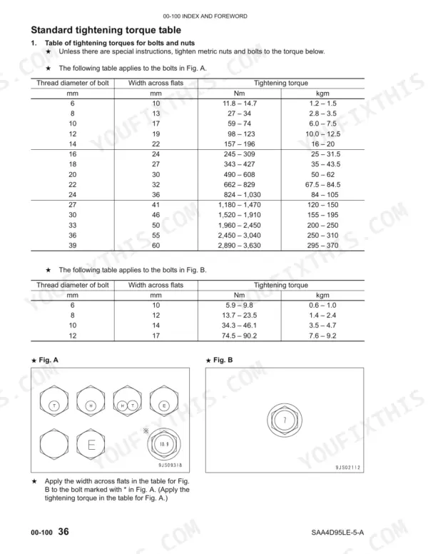
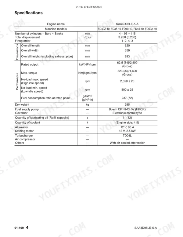

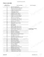
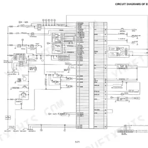
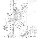
Returning a Komatsu SAA4D95LE-5-A diesel engine to factory tolerance is what the 320 pages of this shop manual PDF (OEM ID 4D95LE-BE3) are for, and it lists the engine against twelve FD series designations, including FD35-10 through FD80-10. Troubleshooting takes up the largest part of the book. It pairs a failure code table with E-mode electrical charts and S-mode mechanical charts that trace a symptom back to its cause. Wiring diagrams show the starting, charging and engine controller circuits, and the common rail fuel system is broken down from the supply pump through to the injectors, sensors and connectors. Hold main journal clearance to 0.043 to 0.103 mm and crankshaft end play to 0.131 to 0.351 mm. At the stand, there's nobody else to ask. The PDF is bookmarked and text-searchable, so it goes with you to the bench, the shop or a laptop, and every clearance and torque value is there before your engine goes back together.
What's Inside This Komatsu SAA4D95LE-5-A Manual
| System | Pages | Key Topics |
|---|---|---|
| Index and Foreword | 1-46 | General Precautions, Preparations for Work, Precautions for Sling Work |
| Specification | 47-60 | Outline, Specifications, Weight Table, Engine Performance Curves |
| Structure, Function and Maintenance Standard | 61-130 | Air Intake and Exhaust System (Turbocharger) |
| Standard Value Table | 131-136 | Standard Service Value Table, Running-In Standard |
| Testing and Adjusting | 137-160 | Testing and Adjusting Tools List, Testing Exhaust Temperature, Valve Clearance, Testing Compression Pressure, Testing Blow-By Pressure, Testing Oil Pressure |
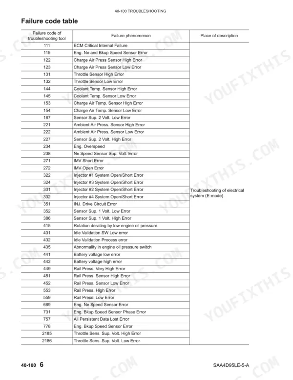
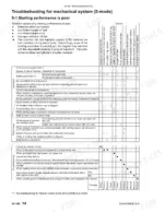
| Troubleshooting | 161-280 | General Information on Troubleshooting, Failure Code Table, Troubleshooting for Mechanical System, Troubleshooting for Electrical System |
| Disassembly and Assembly | 281-320 | How to Read This Manual, Coating Materials List, Special Tools List, Disassembly and Assembly Procedure for Fuel Supply Pump Unit |
Quick Reference Specifications
| Specification | Value | Page |
|---|---|---|
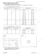
| Holder mounting bolt | 27 – 30 Nm {2.8 – 3.1 kgm} | p. 142 |
| End play | 0.131 – 0.351 mm | p. 80 |
| Clearance of main journal | 0.043 – 0.103 mm | p. 80 |
| Clearance between camshaft and bushing | 0.040 – 0.140 mm | p. 81 |
| Clearance between connecting rod bushing and piston pin | 0.020 – 0.039 mm | p. 83 |
| Air bleeding plug (fuel main filter) torque | 7.8 – 9.8 Nm {0.8 – 1.0 kgm} | p. 153 |
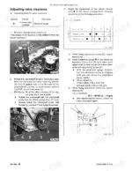
| Intake valve clearance | 0.35 mm | p. 132 |
| Exhaust valve clearance | 0.50 mm | p. 132 |
| Oil temperature | 90 – 110 °C | p. 132 |
| Fan speed | 2,400 ± 60 rpm | p. 132 |
| High-pressure pipe flare nut (Both ends) | 25.5 – 29.4 Nm {2.6 – 3.0 kgm} | p. 143 |
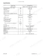
| Engine Rated Output (FD40Z-10, FD35-10, FD40-10, FD45-10, FD50A-10) | 62.5 kW/2,400 rpm | p. 134 |
Komatsu SAA4D95LE-5-A Common Problems This Manual Covers
Komatsu SAA4D95LE-5-A crankshaft main journal clearance or end play beyond standard with abnormal engine noise
Measure main journal clearance against 0.043 to 0.103 mm on page 80, and check crankshaft end play against the 0.13 to 0.35 mm permissible range on page 301. Torque the main cap mounting bolts in three steps following page 300: 112.7 Nm, then back to 0 Nm, then 132.0 Nm. Recheck end play after the final torque.
Manual Section: Structure, Function and Maintenance Standard p. 80Connecting rod crankpin journal clearance or piston pin bushing clearance beyond standard with abnormal engine noise
Measure crankpin journal clearance against 0.029 to 0.089 mm on page 80. Check the clearance between the connecting rod bushing and piston pin against 0.020 to 0.039 mm on page 83. When refitting, torque the rod cap mounting bolts to 39.0 Nm, then turn them a further 90 degrees following page 302. Never skip the angle step.
Manual Section: Structure, Function and Maintenance Standard p. 80Intake or exhaust valve clearance out of adjustment with abnormal noise from the cylinder head
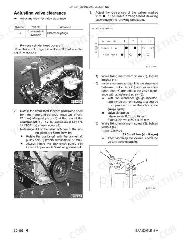
Adjust valve lash following page 140. Set intake clearance to 0.35 ± 0.02 mm and exhaust clearance to 0.50 ± 0.02 mm. Torque the locknut to 39.2 to 49 Nm, then recheck both clearances. Refit the cylinder head cover and torque its mounting nuts to 8.82 ± 0.98 Nm as shown on page 141.
Manual Section: Testing and Adjusting p. 140Low compression pressure on one or more cylinders with poor starting performance
Remove the injector and test compression pressure following the procedure on pages 142 to 143. On reassembly, torque the injector holder mounting bolt to 27 to 30 Nm (page 142). Torque the high-pressure pipe flare nuts at both ends to 25.5 to 29.4 Nm (page 143). Then test the fuel system for leakage before you run it.
Manual Section: Testing Compression Pressure p. 142Air trapped in the fuel circuit after fuel main filter service with engine not starting
Bleed air from the fuel circuit at the air bleeding plug on the fuel main filter, following page 153. Torque the plug to 7.8 to 9.8 Nm. If the engine still will not start, test low-pressure fuel circuit pressure and check the high-pressure circuit for leakage before you start chasing electrical failure codes.
Manual Section: Bleeding Air from Fuel Circuit p. 153Coolant temperature sensor failure code with controller holding coolant temperature at a fixed value
Check the coolant temperature sensor and its circuit using the E-mode troubleshooting and the wiring diagram. According to page 207, the controller sets coolant temperature to a fixed 90°C after a sensor error and keeps the engine running. A steady reading therefore does not prove the engine is cool. Clear the fault before any load testing.
Manual Section: Troubleshooting for Electrical System (E-mode) p. 207Frequently Asked Questions
What is the procedure for troubleshooting failure code E-43, which indicates an engine backup speed sensor error?
Failure code [778] indicates an abnormality in the engine backup speed sensor circuit. To troubleshoot, check the wiring harness for disconnections or short circuits, and inspect the sensor mount directly for defects. If these checks do not resolve the issue, the engine backup speed sensor itself may be defective. p. 266
What does failure code E-7 [143] mean for engine oil pressure on the Komatsu SAA4D95LE-5-A?
Failure code [143] indicates that the engine oil pressure is below the operating range. The controller will limit output and continue operation by limiting the fuel injection rate and engine speed. You should investigate the cause of the low oil pressure and check for damages, then repair or replace the damaged parts. p. 205
What should I check if I receive failure code E-5 [131] for a throttle sensor high error?
Failure code [131] indicates that the signal voltage in the throttle sensor circuit is abnormally high. You should check the fuel control dial for internal trouble, inspect the wiring harness for disconnections or short circuits, and verify the power supply voltage, which should be between 4.75 – 5.25 V. p. 202
What is the tightening torque for the cylinder head mounting bolts on the Komatsu SAA4D95LE-5-A?
The cylinder head mounting bolts require a multi-step tightening process. The first step is 68.6 ± 9.8 Nm (7.0 ± 1.0 kgm), the second step is 107.8 ± 4.9 Nm (11.0 ± 0.5 kgm), and the third step is to mark the bolt head and cylinder head, then turn the bolt 90 (+30/0)° to tighten. p. 308
What is the standard intake and exhaust valve clearance on the Komatsu SAA4D95LE-5-A engine?
The standard valve clearance for the intake valve is 0.35 ± 0.02 mm, and for the exhaust valve, it is 0.50 ± 0.02 mm. These measurements should be taken when the engine is either hot or cold. p. 140
Will this Komatsu SAA4D95LE-5-A Shop Manual download right away?
A 320-page Shop Manual in searchable PDF format, available the moment you complete checkout. View on computer, tablet, or phone, with no shipping wait.
Is this Komatsu SAA4D95LE-5-A manual print-friendly?
Yes. Many mechanics print the section they need for their own shop and bring it to the bench.
Reviews
There are no reviews yet.