
A swing motor that drifts, a travel motor that loses power, a pump controller throwing codes onto the monitor panel: this Komatsu PC228US-3, PC228USLC-3 shop manual PDF (OEM ID SEBM023104) is the 598-page factory book for tracing those faults on both hydraulic excavators. Troubleshooting fills the largest share, tracing electrical fault modes through the pump controller, monitor panel and connector pin tables before full hydraulic and electrical circuit diagrams close the book. Disassembly chapters take the final drive, travel motor, swing machinery and control valve apart, while testing procedures handle hydraulic pressure, track shoe tension and air bleeding. Confirm the PPC oil pressure switch turns ON at 0.5 ± 0.1 MPa, and torque the swing machinery mounting bolts to 590 to 608 N·m. Guessing costs you a seal kit and a second teardown. Bookmarked, searchable pages help you confirm the failed component, so the right part gets ordered the first time.
What's Inside This Komatsu PC228US-3, PC228USLC-3 Manual
| System | Pages | Key Topics |
|---|---|---|
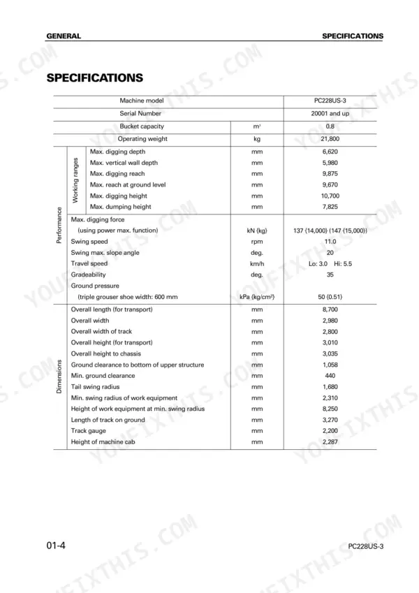
| General | 27-38 | Specification Dimension Drawings, Specifications, Weight Table |
| Structure, Function and Maintenance Standard | 39-210 | Track Frame and Recoil Spring, Hydraulic Pump, Control Valve, Swing Motor, Travel Motor |
| Standard Value Tables | 211-230 | Engine Standard Values, Chassis Standard Values, Electrical Related Parts Standard Values |
| Testing and Adjusting Procedures | 231-266 | Engine Speed Measurement, Valve Clearance Adjustment, Hydraulic Pressure Testing, Track Shoe Tension, Air Bleeding Procedures |
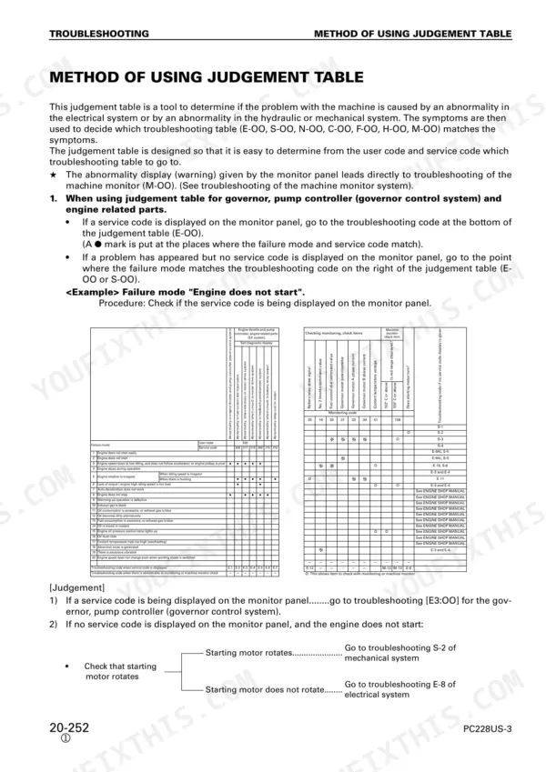
| Troubleshooting Introduction and Methods | 267-300 | Troubleshooting Sequence, Maintenance Precautions, Connector Types, Connector Pin Tables |
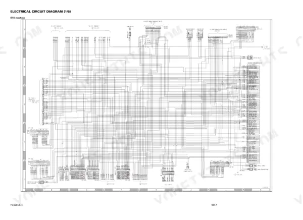
| Troubleshooting - Electrical Systems (N, E, C, F, M Modes) | 301-486 | Communication Abnormality, Engine Throttle and Pump Controller, Monitor Panel System, Electrical Circuit Diagrams |
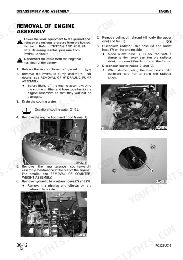
| Disassembly and Assembly | 487-580 | Engine Assembly, Final Drive and Travel Motor Assembly, Swing Motor and Swing Machinery Assembly, Control Valve Assembly |
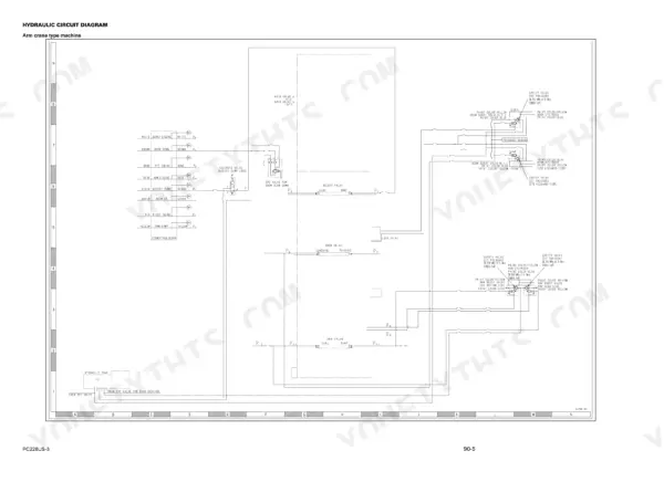
| Others | 581-598 | Hydraulic Circuit Diagram, Electrical Circuit Diagram |
Quick Reference Specifications
| Specification | Value | Page |
|---|---|---|
| All Models | ||
| Balance stop position pressure range | 0.69 MPa to 2.2 MPa | p. 72 |
| EPC valve output pressure range | 0 MPa to 2.9 MPa | p. 72 |
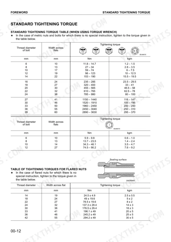
| Swing machinery mounting bolt | 590 - 608 N·m | p. 526 |
| Swing motor assembly mounting bolt torque | 58.8 - 73.5 N·m | p. 533 |
| PPC oil pressure switch Operating (ON) pressure | 0.5 ± 0.1 MPa {5.0 ± 1.0 kg/cm²} | p. 196 |
| PPC oil pressure switch Resetting (OFF) Pressure | 0.3 ± 0.5 MPa {3.0 ± 0.5 kg/cm²} | p. 196 |
| Track roller plug torque | 14.9 ± 5.0 N·m | p. 543 |
| Engine oil pan capacity (refill) | 24 L | p. 38 |
| Hydraulic system capacity (refill) | 126 L | p. 38 |
| Fuel tank capacity | 320 L | p. 38 |
| PC228US-3 | ||
| Operating weight | 21,800 kg | p. 30 |
| PC228USLC-3 | ||
| Operating weight | 23,100 kg | p. 32 |
Komatsu PC228US-3, PC228USLC-3 Common Problems This Manual Covers
Komatsu PC228US-3 governor motor drive or fuel control dial input fault with engine speed irregular and lack of power
Check the controller power source first, then test the governor motor drive system and fuel control dial input using the E mode procedures. Measure engine speed with the Testing and Adjusting procedures starting on page 231 before you blame the pump side. Rule out the controller power feed before you order parts.
Manual Section: Engine Throttle and Pump Controller (E mode)PC-EPC or LS-EPC solenoid fault code from the pump controller with work equipment slow
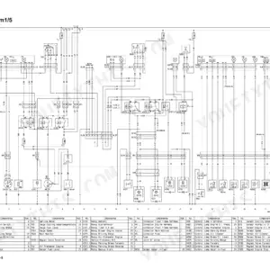
Test the PC-EPC and LS-EPC solenoid circuits and the pump pressure sensor with the C mode procedures before you touch the pump. Verify that EPC valve output pressure stays within 0 to 2.9 MPa, as listed on page 72. While you're in there, check the connectors against the wiring diagram on page 587.
Manual Section: Engine Throttle and Pump Controller (C mode) p. 72Hydraulic pump and control valve check for work equipment slow, excessive hydraulic drift, and abnormal noise
Check the hydraulic oil level first. The system takes 126 L at refill, per page 38. Test hydraulic pressures with the Hydraulic Pressure Testing procedure in the Testing and Adjusting section starting on page 231. Then trace the circuit on the hydraulic schematic on page 585 to separate a pump problem from a control valve problem.
Manual Section: Hydraulic System TroubleshootingSwing machinery and final drive check turns up swing motor or travel motor leakage
Verify the leak with the hydraulic troubleshooting checks, then remove the swing motor following the Swing Motor and Swing Machinery Assembly procedure. Torque the motor mounting bolts to 58.8 to 73.5 N·m (page 533) and the swing machinery bolts to 590 to 608 N·m (page 526). Refill the swing machinery with 6.6 L of oil.
Manual Section: Disassembly and Assembly p. 533Controller communication abnormality with E218 communication error code showing on the monitor panel
Check connector contact using the connector pin tables in the Troubleshooting Introduction on page 267, then run the N mode communication abnormality procedure. Trace the circuit on the wiring diagram on page 587 and confirm what the error code means before you replace any controller.
Manual Section: Communications Abnormality (N mode)Pump controller F mode check shows PPC oil pressure switch input signal abnormal
Test how the PPC oil pressure switch operates. It should turn ON at 0.5 ± 0.1 MPa, as listed on page 196, and reset as pressure drops. Then verify the pressure switch signals at the controller using the F mode input signal procedures before you replace the switch.
Manual Section: Engine Throttle and Pump Controller (F mode) p. 196Frequently Asked Questions
How do I clear the service codes from the monitor panel memory on the PC228US-3?
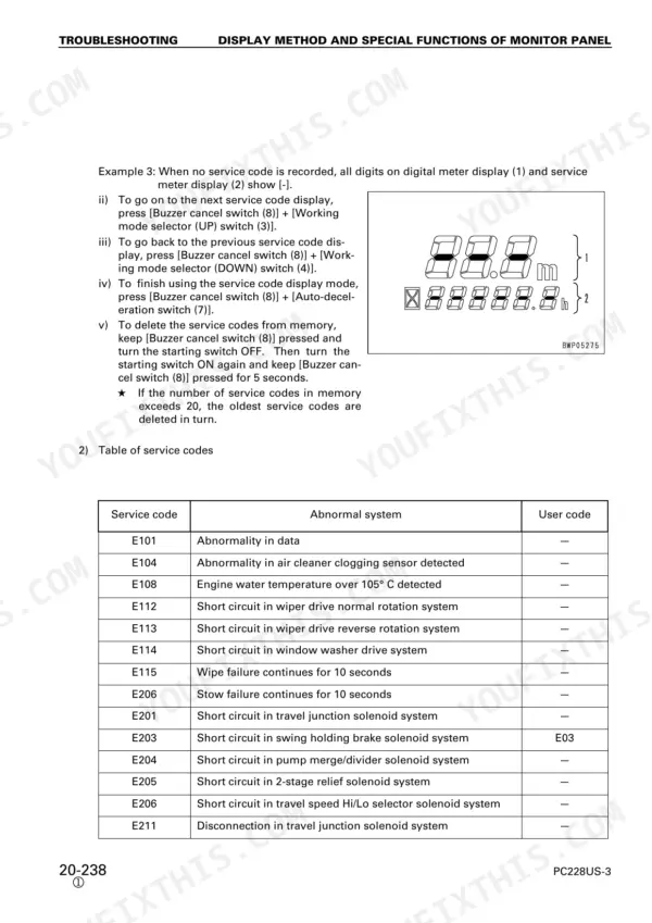
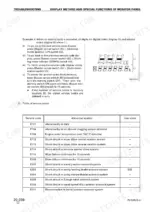
To delete service codes from memory, keep the buzzer cancel switch (8) pressed while turning the starting switch OFF. Then, turn the starting switch ON again and continue to keep the buzzer cancel switch (8) pressed for 5 seconds. p. 304
What is the track roller plug tightening torque on the Komatsu PC228US-3?
Tighten the track roller plug to 14.9 ± 5.0 N·m {1.5 ± 0.5 kgm}, as given in the track roller assembly procedure on page 543. Check the filler port for air leakage at the seal before you refit the plug.
What are the replacement specifications for the LS-EPC solenoid on the Komatsu PC228US-3?
The LS-EPC solenoid resistance value is 5 - 15 ohms. If the resistance is outside this range, the solenoid should be replaced. p. 397
What is the hydraulic oil capacity of the Komatsu PC228US-3?
The hydraulic system holds 185 L specified, and 126 L is the refill amount at an oil change, per the fuel, coolant and lubricants table on page 38.
What is the standard valve clearance for the intake and exhaust valves on the Komatsu PC228US-3 engine?
The standard valve clearance for both intake and exhaust valves at normal temperature is 0.25 mm for intake and 0.51 mm for exhaust. p. 212
Is this Komatsu PC228US-3 manual a download or a disc?
Straight to your device: 598 pages of searchable Shop Manual, downloadable the moment payment goes through.
Am I free to print this Komatsu PC228US-3 Shop Manual?
Yes. Printing works from any reader and any printer, for your own shop use.

Reviews
There are no reviews yet.