
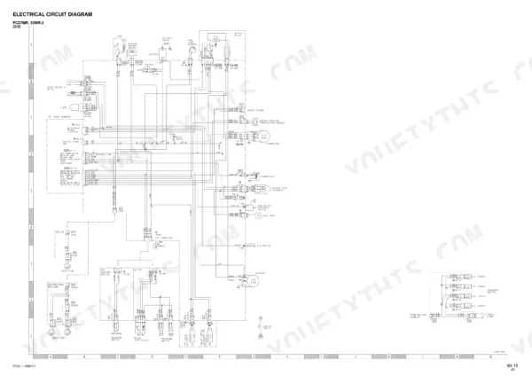
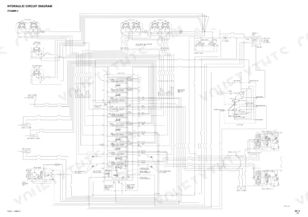
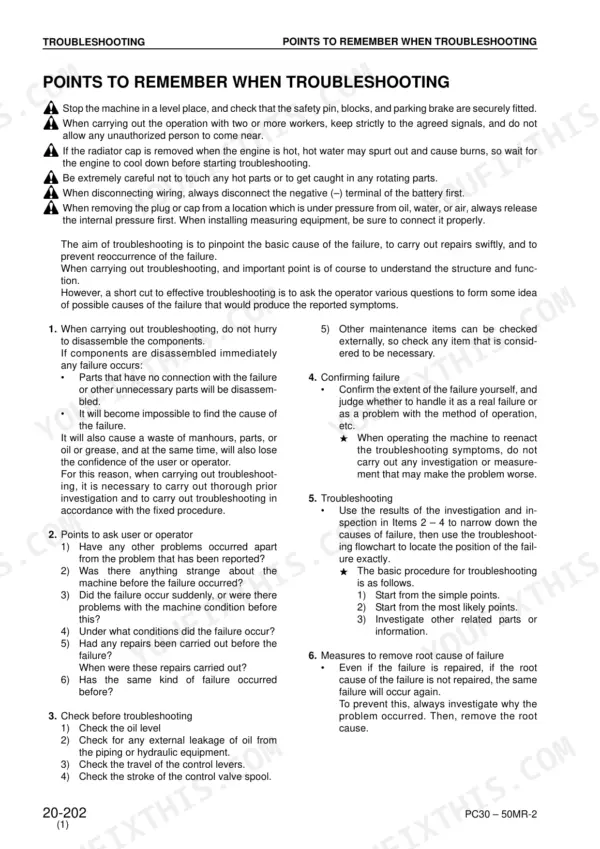
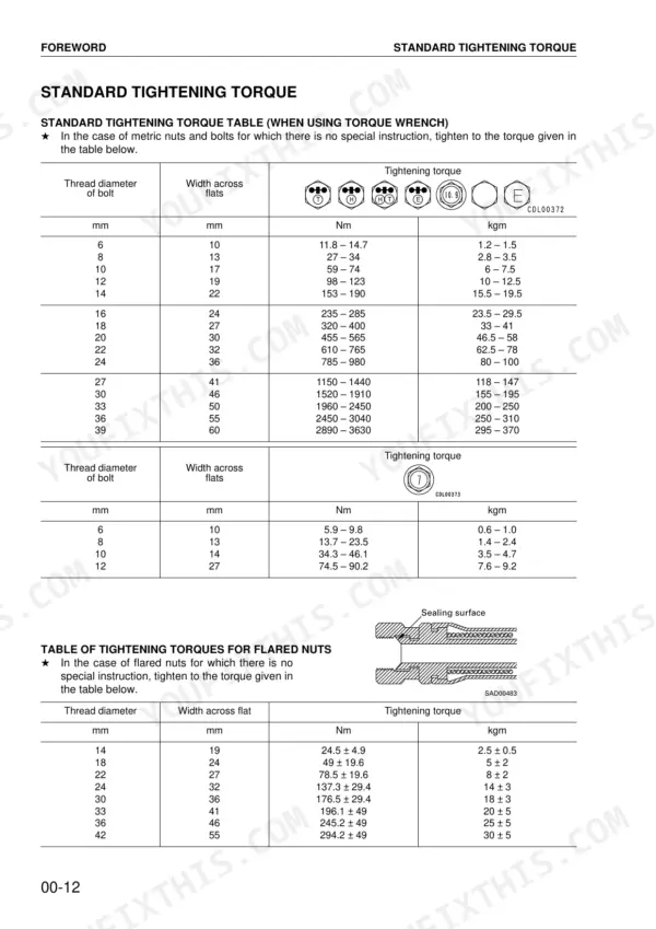
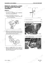
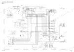
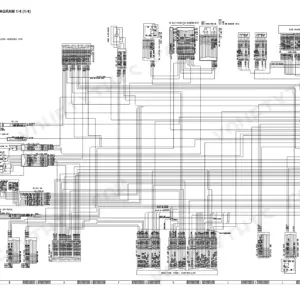
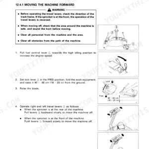
Before you crack a hose fitting or pull a travel motor, this 630-page Komatsu PC35MR-2 shop manual PDF (SEBM032411) belongs open on the bench, covering five MR-2 hydraulic excavator variants from the PC27MR-2 to the PC50MR-2. Troubleshooting fills nearly a third of the book. It is split into electrical E-mode, hydraulic and mechanical H-mode, and monitor panel M-mode checks for travel deviation, swing performance, hydraulic drift and engine start failure. Structure, Function and Maintenance Standard is the largest section and walks through swing machinery, track frame and control valve. The back of the manual carries hydraulic and electrical circuit diagrams for tracing a fault from pump to cylinder. Run track shoe bolts on the PC27MR-2, PC30MR-2 and PC35MR-2 to 130 to 145 Nm, and a 22 mm flared hose nut to 78.5 ± 19.6 Nm. Guess wrong and you pay twice: new hose, second teardown. Bookmarks and a live text layer take you to the right E-mode or H-mode table in seconds.
What's Inside This Komatsu PC27MR-2–PC50MR-2 Manual
| System | Pages | Key Topics |
|---|---|---|
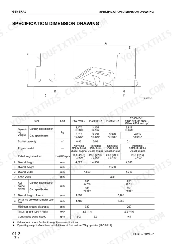
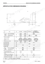
| General | 27-60 | Specification Dimension Drawing, Working Range Drawing, Specifications, Weight Table, Lubricants, Fuel and Coolant Specifications |
| Structure, Function and Maintenance Standard | 61-269 | Cooling System, Swing Machinery, Track Frame, Control Valve |
| Standard Value Tables | 270-295 | Engine Related Parts, Chassis Related Parts, Performance of Hydraulic Pump, Machine Posture for Performance Measurement |
| Testing and Adjusting Procedures | 296-355 | Engine Speed Measurement, Exhaust Gas Color, Valve Clearance, Compression Pressure, Alternator Belt Tension, Air Conditioner Compressor Belt Tension |
| Troubleshooting - Electrical System (E-Mode) | 356-447 | Troubleshooting Sequence, Wiring Harness Handling, Fuse Box Connection, Engine Start Failure, Windshield Wiper, Air Conditioner |
| Troubleshooting - Hydraulic and Mechanical System (H-Mode) | 448-483 | Work Equipment Speed/Power, Travel Deviation, Swing Performance, Blade Operation, Hydraulic Drift |
| Troubleshooting - Monitor Panel System (M-Mode) | 484-543 | Monitor Panel Self-Check, Alarm Buzzer, Engine Oil Pressure Caution, Charge Level Caution, Coolant Temperature Gauge, Fuel Level Gauge |
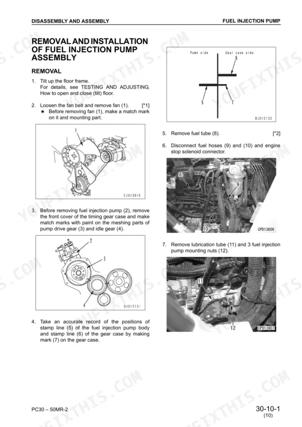
| Disassembly and Assembly | 544-618 | Removal and Installation of Fuel Injection Pump Assembly, Removal and Installation of Radiator and Hydraulic Oil Cooler Assembly |
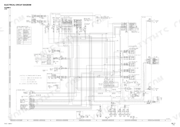
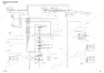
| Others | 619-630 | Hydraulic Circuit Diagram, Electrical Circuit Diagram |
Quick Reference Specifications
| Specification | Value | Page |
|---|---|---|
| All Models | ||
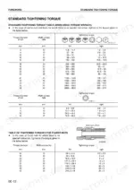
| Tightening torque for flared nuts | 24.5 ± 4.9 Nm to 294.2 ± 49 Nm | p. 16 |
| Tightening torque for O-ring boss plugs | 5.88-8.82 Nm to 274.4-367.5 Nm | p. 17 |
| PC27MR-2, PC30MR-2, PC35MR-2 | ||
| Tightening torque of shoe bolt | 130 – 145 Nm {13 – 14.5 kgm} | p. 86 |
| Hydraulic Tank Capacity (PC27, 30, 35MR-2) | 30L | p. 91 |
| PC27MR-2, PC30MR-2 | ||
| Main relief valve adjustment screw adjustment amount per turn (PC27, 30MR-2) | 12.6 MPa {128 kg/cm2} | p. 322 |
| PC35MR-2, PC40MR-2, PC50MR-2 | ||
| Main relief valve adjustment screw adjustment amount per turn (PC35, 40, 50MR-2) | 19.6 MPa {200 kg/cm2} | p. 323 |
| PC40, 50MR-2 | ||
| Revolving frame assembly mounting bolt torque | 98 – 123 Nm | p. 600 |
| Swing circle assembly mounting bolt torque | 98 – 122.5 Nm | p. 601 |
| PC27MR-2, PC35MR-2 | ||
| Engine Oil Capacity (PC27, 35MR-2) | 7.7L | p. 59 |
| PC40MR-2, PC50MR-2 | ||
| Engine Oil Capacity (PC40, 50MR-2) | 8.0L | p. 59 |
Komatsu PC27MR-2–PC50MR-2 Common Problems This Manual Covers
Komatsu PC35MR-2 engine will not start, starting motor does not rotate with key in START
Check that the PPC lock lever is in LOCK. The starting circuit is interlocked and will not crank in FREE (page 414). Measure battery voltage against min. 12 V and electrolyte specific gravity against min. 1.26. Inspect the 45-A fusible link and fuses (12) and (13). A blown one points to a grounding fault. Then test relay R1 coil resistance against 86 to 106 ohms.
Manual Section: Troubleshooting for Electric System (E-mode) p. 414Work equipment still moves when PPC lock lever is set in LOCK position
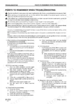
Check the fuse box first. Fuse No. 2 (10A) feeds the PPC lock solenoid relay and fuse No. 3 (10A) feeds the PPC lock switch (page 412). Verify the power supply at each one, then work through E-3 in the E-mode section that starts on page 411. When you reproduce the fault, do not run any test that could make it worse (page 357). Hang warning signs on the control levers (page 7).
Manual Section: Troubleshooting for Electric System (E-mode) p. 411Whole work equipment, travel system, swing system and blade do not work at all
Check the hydraulic tank oil level first, then warm the oil to 45 to 55°C before you test anything (page 456). Use the H-3 table on page 455 to sort out which systems are dead, then go to the matching item: work equipment and travel, swing and blade, or work equipment and blade. Diagnose before you disassemble any component (page 357).
Manual Section: Troubleshooting for Hydraulic and Mechanical System (H-mode) p. 455Whole work equipment speed slow or power weak with hydraulic oil warmed to operating temperature
Verify the hydraulic tank oil level and warm the oil to 45 to 55°C before you judge speed or power (page 456). Before fitting a gauge, run the engine at low idle and lower the work equipment to the ground without relieving the cylinders at stroke end, then stop the engine (page 349). On PC35, 40 and 50MR-2, one turn of the main relief adjusting screw changes pressure by 19.6 MPa. Torque the locknut to 39 to 49 Nm (page 323).
Manual Section: Troubleshooting - Hydraulic and Mechanical System (H-Mode) p. 448Engine oil pressure caution lamp flashes on monitor panel while engine is running
Check for a real oil pressure drop first by running S-12 in the engine troubleshooting section (page 520). If engine pressure is good, disconnect connector T-M3 and check the caution as the M-4 chart on page 494 directs. If the monitor panel and wiring harnesses test normal, replace the engine oil pressure switch.
Manual Section: Troubleshooting for Monitor Panel System (M-mode) p. 494Charge level caution lamp flashes on monitor panel while engine is running
Measure battery voltage with the engine stopped against 10 to 15 V, then measure alternator voltage at 1/2 throttle or above against 13.5 to 14.5 V (page 367). The caution comes on when charge voltage falls below battery voltage (page 267). If alternator output falls short, work through M-5 on page 495 for PC27, 30 and 35MR-2.
Manual Section: Troubleshooting for Monitor Panel System (M-mode) p. 495Frequently Asked Questions
How do you bleed the hydraulic system after changing hoses or filters?
After replacing hydraulic components, bleed the air by starting the engine and running it at low idle. Operate the work equipment control lever to operate the hydraulic cylinders 4 to 5 times, stopping the cylinder 100 mm from the end of their stroke. Then, operate the hydraulic cylinder 3 to 4 times to the end of its stroke. Finally, run the engine at normal speed. See page 548 for the full procedure. p. 548
What is the tightening torque for the cylinder head of the hydraulic cylinder on a PC30MR-2?
For a PC30MR-2, the tightening torque for the cylinder head is 588 ± 59.0 Nm {60 ± 6.0 kgm} for the boom and boom swing cylinders, 677 ± 67.5 Nm {69 ± 6.9 kgm} for the arm and bucket cylinders, and 637 ± 63.5 Nm {65 ± 6.5 kgm} for the blade cylinder. p. 108
What is the standard valve clearance for the engine on a PC30MR-2?
The standard valve clearance for both the intake and exhaust valves on the PC30MR-2 engine (3D84E-5N) is 0.20 mm at normal temperature. p. 272
What is the capacity of the hydraulic tank for a PC40MR-2 or PC50MR-2?
The hydraulic tank capacity for the PC40MR-2 and PC50MR-2 is 33 liters, with an oil amount of 20 liters. p. 92
Do I get instant access to this Komatsu PC27MR-2 Shop Manual?
All 630 pages arrive as one searchable PDF at checkout. Read it at the desk, then take the phone out to the machine.
Can I print pages of this Komatsu PC27MR-2 manual for my own shop?
Yes. Print the sections you need to take out to the shop for your own use. Standard letter or A4 paper works.
Are hydraulic system diagrams in this Komatsu PC27MR-2 Shop Manual?
Full hydraulic system diagrams are included, covering circuits, valve locations, and hydraulic component specs for the Komatsu PC27MR-2 & variants. Page 620 carries one of them.



Reviews
There are no reviews yet.