
The PC300LC-8 or PC300HD-8 is parked with the boom down and a code on the monitor. A crew stands around waiting on trucks that aren't getting loaded. This Komatsu Shop Manual CEBM018703 (August 2011) covers PC300LC-8 serial A90001 and up and PC300HD-8 serial A87001 and up, both with the SAA6D114E-3 engine.
The book follows Komatsu's layout: general and specifications, structure and function, standard value tables, testing and adjusting, then troubleshooting by failure code, E-mode electrical and H-mode hydraulic checks. It covers CLSS valve operation, the HPV125+125 pump, the final drive, swing machinery and the undercarriage. The H-mode checks give you real numbers to test against, like main relief at 340 - 375 kg/cm2 (4,836 - 5,333 psi) with arm IN.
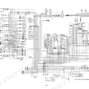
The disassembly chapters carry the torques and component weights. Fold-out hydraulic and electrical circuit diagrams finish the book. Track the fault down, fix it and get the bucket back in the dirt.
What's Inside This Komatsu PC300LC-8, PC300HD-8 Manual
| System | Pages | Key Topics |
|---|---|---|
| Front Matter, Safety and General Service Data | 1-32 | Revised Pages, Safety, How to Read the Shop Manual, Hoisting Instructions, Push Pull Coupler, Coating Materials, Standard Tightening Torque, Electric Wire Code, Conversion Tables |
| General: Specifications | 33-42 | Specification Dimension Drawings, Specifications for PC300LC-8 and PC300HD-8, SAA6D114E-3 Engine Data, Weight Table, Fuel, Coolant and Lubricants |
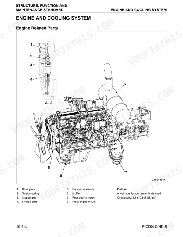
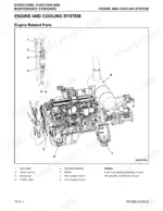
| Engine, Cooling System and Power Train | 43-61 | Engine Related Parts, Radiator, Oil Cooler and Aftercooler, Power Train, Final Drive, Sprocket, Swing Machinery, Swing Circle |
| Undercarriage and Frame | 62-81 | Track Frame and Recoil Spring, Idler, Carrier Roller, Track Roller, Track Shoe, Triple Grouser Shoe |
| Hydraulic System: Tank, Pump and Control Valve | 82-119 | Hydraulic Equipment Layout Drawing, Hydraulic Tank and Filter, HPV125+125 Hydraulic Pump, Control Valve |
| Hydraulic System: CLSS and Valve Functions | 120-170 | CLSS Closed Center Load Sensing System, Valve Functions and Operation |
| Hydraulic System: Valve Control and Cylinders | 171-239 | Valve Control, PPC Valves, Solenoid Valves, Hydraulic Cylinder |
| Work Equipment and Electrical System | 240-256 | Work Equipment, Air Conditioner Piping, Engine Control, Sensors |
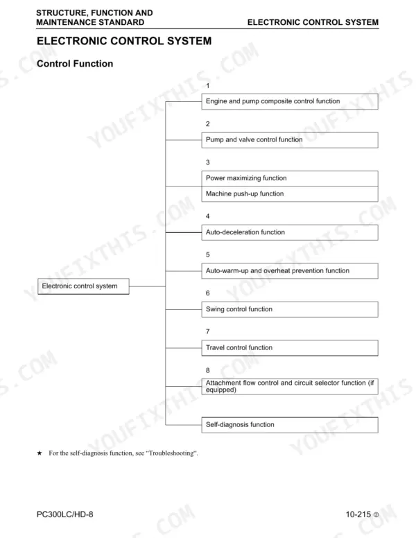
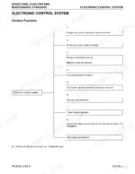
| Electronic Control System | 257-284 | System Diagram, Engine and Pump Control, Pump and Valve Control, Power Maximizing and Machine Push-Up, Auto-Deceleration, Auto-Warm-Up and Overheat Prevention, Swing and Travel Control, Attachment Flow Control |
| Monitor System and Komtrax | 285-316 | Machine Monitor, Komtrax Communication Modem TH300 |
| Standard Value Tables | 317-326 | Engine Related Standard Values (Engine Speeds, Boost Pressure, Valve Clearance, Compression, Blow-By, Oil Pressure), Chassis Related Standard Values (Hydraulic Pressures, Swing, Travel, Work Equipment) |
| Testing and Adjusting: Engine and Hydraulic Pressures | 327-391 | Chassis Service Tools, Engine Tests, Belt Tension, Swing Circle Bearings, Track Shoe Tension, Work Equipment, Swing and Travel Oil Pressure, Pump PC and LS Pressure, Solenoid and PPC Valve Output Pressure, Hydraulic Drift, Releasing Pressure, Bleeding Air, Diode Inspection |
| Testing and Adjusting: Machine Monitor Special Functions | 392-466 | Machine Monitor Service Menu, Abnormality Record and Reset, Handling Voltage Circuit of Engine Controller, Preparation for Electrical Troubleshooting, Testing Diodes, PM Clinic Service |
| Troubleshooting: Failure Codes Table and Fuse Locations | 467-477 | Failure Codes Table with Action Codes, Device in Charge, Fuse Locations |
| Troubleshooting: General Information | 478-538 | Points to Remember, Sequence of Events, Handling Electric Equipment and Hydraulic Components, Connectors for Tier 3 Engines, Checks Before Troubleshooting, Connector Pin Number Tables, T-Adapter Table |
| Troubleshooting by Failure Code | 539-737 | Troubleshooting of Each Displayed Failure Code, Including Engine Controller CA Codes |
| Troubleshooting: E-Mode (Electrical System) | 738-797 | E-1 Engine Does Not Start Through E-31 Horn Does Not Sound: Auto-Decelerator, Preheater, Power Max, Machine Monitor Display, Gauges, Wiper, Komtrax, Air Conditioner, Travel Alarm |
| Troubleshooting: H-Mode (Hydraulic and Mechanical) | 798-826 | H-1 All Work Equipment Lacks Power Through H-27: Engine Stall, Boom, Arm and Bucket Slow, Hydraulic Drift, Time Lag, Travel Swerve and Slow Travel, Swing Acceleration and Overrun |
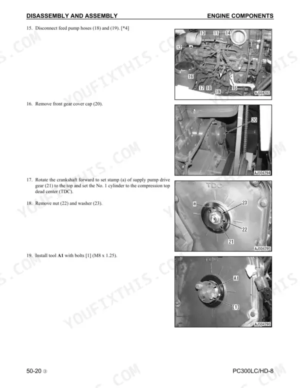
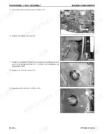
| Disassembly and Assembly: Tools, Engine Components and Cooling | 827-884 | How to Read, Special Tools List and Sketches, Connector Repair, Engine Components, Radiator, Hydraulic Oil Cooler, Aftercooler, Engine and Hydraulic Pump |
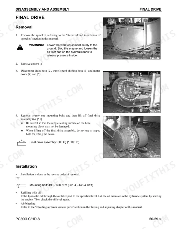
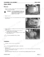
| Disassembly and Assembly: Undercarriage, Swing and Hydraulic Components | 885-962 | Final Drive, Swing Motor and Machinery, Swing Circle, Rollers, Idler, Recoil Spring, Sprocket, Track Shoe, Revolving Frame, Counterweight, Center Swivel Joint, Hydraulic Tank, Control Valve, Hydraulic Pump, PPC Valves, Hydraulic Cylinder, Work Equipment |
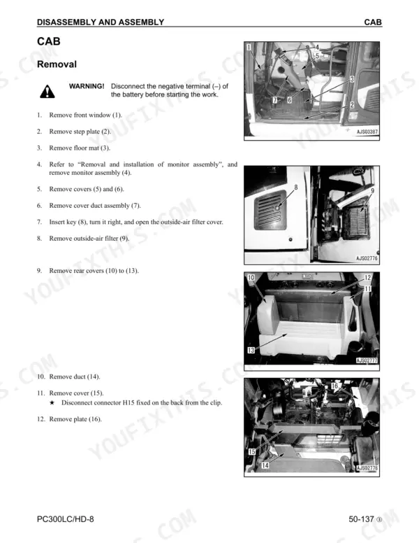
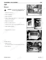
| Disassembly and Assembly: Cab and Electrical System | 963-1002 | Operator Cab, Electrical System Components |
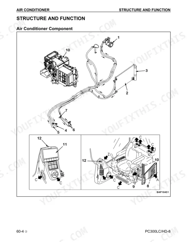
| Air Conditioner | 1003-1088 | Components, Refrigerating Cycle, Air Conditioner Unit, Compressor, Condenser, Testing with Self-Diagnosis, Troubleshooting Charts, E Mode, Gauge Pressure, Compressor Oil, Desiccant Replacement |
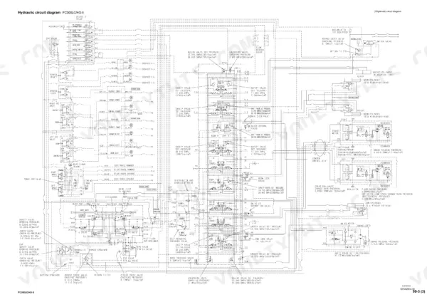
| Diagrams and Drawings | 1089-1097 | Hydraulic Circuit Diagram, Electrical Circuit Diagram-, Electrical Connector Arrangement Diagram |
Quick Reference Specifications
| Specification | Value | Page |
|---|---|---|
| Engine | SAA6D114E-3, 6 - 114 x 135 mm, 8.27 L {8,270 cc} | p. 37 |
| Flywheel horsepower | 183.9/1,980 kW/rpm {250/1,980 HP/rpm} | p. 37 |
| Max. torque | 1,108/1,450 Nm/rpm {113/1,450 kgm/rpm} | p. 37 |
| Operating weight | PC300LC-8 32,830 kg; PC300HD-8 36,736 kg | p. 36 |
| Bucket capacity | 1.4 m³ | p. 36 |
| Travel speed (Hi) | PC300LC-8 5.5 km/h; PC300HD-8 4.9 km/h | p. 36 |
| Hydraulic pump | HPV125+125, 267.5 x 2 L/min, set pressure 37.8 MPa {380 kg/cm²} | p. 37 |
| Hydraulic system oil (specified / refill) | 365 L / 188 L | p. 41 |
| Engine oil pan (specified / refill) | 40 L / 35 L | p. 41 |
| High idling / low idling | 2,050 ±50 rpm / 1,000 ±25 rpm | p. 318 |
| Valve clearance (intake / exhaust) | 0.305 mm / 0.559 mm | p. 318 |
| Unload pressure | 39.7 ±10.1 kg/cm² (565 ±144 psi) | p. 320 |
| Track shoe tension clearance | 10 - 30 mm (0.4 - 1.2 in) | p. 362 |
Komatsu PC300LC-8, PC300HD-8 Common Problems This Manual Covers
Engine will not start
Work through E-1 in order. Confirm the batteries show min. 24 V and specific gravity of min. 1.26. Then check fuse No. 3, fuse No. 17 and fusible links F04/F05. Next check starting switch H15, safety lock switch S14 and starting motor cutout relays R06/R07 before you move on to the starting motor.
Manual Section: Troubleshooting: E-Mode (Electrical System), E-1 Engine does not start p. 740All work equipment lacks power, pump suspected
Follow H-1 before ordering a pump. Check unload pressure at 40±10 kg/cm2 (568±142 psi) with all levers in neutral. Then check main relief at 340 - 375 kg/cm2 (4,836 - 5,333 psi) with arm IN, and control circuit basic pressure at 29 - 35 kg/cm2 (413 - 497 psi). Low control pressure sends you to the pilot circuit, not the pump.
Manual Section: Troubleshooting: H-Mode (Hydraulic and Mechanical), H-1 All work equipment lacks power p. 802Engine speed drops sharply or stalls under hydraulic load
H-2 starts with main relief at 340 - 375 kg/cm2 (4,836 - 5,333 psi) with arm IN. Next, turn swing lock ON and hold arm IN at relief. Then read the PC valve output pressure. It should be about 3/5 of pump discharge. The LS valve output should also be about 3/5 of pump discharge. If either stays off after adjustment, H-2 has you check that valve directly.
Manual Section: Troubleshooting: H-Mode (Hydraulic and Mechanical), H-2 Engine speed drops or stalls p. 804Arm is slow or lacks power
Check the left PPC valve output first. It should be min. 28 kg/cm2 (398 psi) on arm IN or OUT. Then check the merge-divider solenoid output at 29 - 35 kg/cm2 (413 - 497 psi). If both are good, H-8 moves on to the pump merge-divider valve, the arm control valve spool and the pressure compensation and regeneration valves.
Manual Section: Troubleshooting: H-Mode (Hydraulic and Mechanical), H-8 Arm speed is slow or lacks power p. 808Frequently Asked Questions
How do I reset error codes on a Komatsu PC300LC-8 or PC300HD-8?
Go into the machine monitor service menu and open the abnormality record. Electrical system codes clear from the Electrical Sys. Error Reset screen. Press [F6] to execute the reset. The mechanical system abnormality record cannot be reset, so that history stays on the machine. The Testing and Adjusting chapter on machine monitor special functions takes you through each screen in order. p. 421
What do the failure codes on the PC300LC-8 and PC300HD-8 monitor mean?
The failure codes table lists the action code, failure code, trouble description and device in charge for each fault. E10 with CA111 is EMC Critical Internal Failure. E11 with CA122 is Chg Air Press Sensor High Error. B@BAZG flags Eng. Oil Press. Low. The Troubleshooting by Failure Code chapter then gives a step-by-step check for every displayed code, including the engine controller CA codes. p. 471
What are the track tension and final drive bolt specs on the PC300LC-8 and PC300HD-8?
Track shoe tension is set by clearance, not torque. Standard is 10 - 30 mm (0.4 - 1.2 in) between a straight bar and the track shoe. Add grease through the fitting to tighten. To loosen, open the valve no more than 1 turn and let grease out. Final drive mounting bolts take 490 - 608 N•m (361.4 - 448.4 lbf ft). The final drive assembly weighs 500 kg (1,103 lb), so rig it properly. p. 362
What should I check on a PC300LC-8 or PC300HD-8 before I condemn the main pump?
Start at H-1 in the H-mode section. Unload pressure should read 40±10 kg/cm2 (568±142 psi) with all levers in neutral. Main relief should be 340 - 375 kg/cm2 (4,836 - 5,333 psi) with arm IN. Control circuit basic pressure should be 29 - 35 kg/cm2 (413 - 497 psi). If all of those pass, run the pump PC and LS pressure checks in Testing and Adjusting before you condemn the HPV125+125. p. 802
What engine speeds and valve clearances should the SAA6D114E-3 show?
High idle is 2,050 ±50 rpm, low idle is 1,000 ±25 rpm and rated speed is 1,950 rpm. Valve clearance is 0.305 mm intake and 0.559 mm exhaust at normal temperature. The standard value tables also cover boost pressure, compression, blow-by and oil pressure. p. 318



Reviews
There are no reviews yet.