
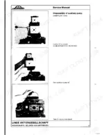
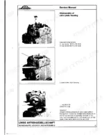
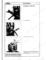
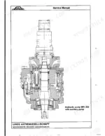
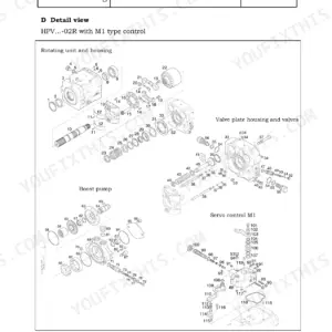
A BPV 200 that drifts off neutral or goes soft under load rarely tells you why until it is on the bench in pieces, and the Linde BPV 200 Service Manual PDF, 60 pages on this variable hydraulic pump, runs that teardown in order: auxiliary pump, filter flange, valves, valve plate housing, control cover, pilot valve. Assembly takes most of the book, from drive shaft bearing setup through swash plate, control cylinder setting, retainer determination and the mechanical neutral position. Valve plate housing work covers the high pressure relief and boost pressure valves; the cartridge filter and double filter flange get their own sequence. Hold axial play between retainer plate and holding plate to 0.01 to 0.03 mm, then pull the pilot housing fixing screws to 86 Nm. Guessing costs a second teardown and a scored valve plate. Bookmarked and searchable, it puts the measurement in front of you before you order, so you buy the right part once.
What's Inside This Linde BPV 200 Manual
| System | Pages | Key Topics |
|---|---|---|
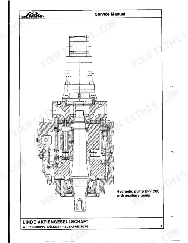
| Variable Hydraulic Pump BPV 200 | 1-2 | Auxiliary Pump, Filter Flange, Valves, Valve Plate Housing, Control Cover, Pilot Valve |
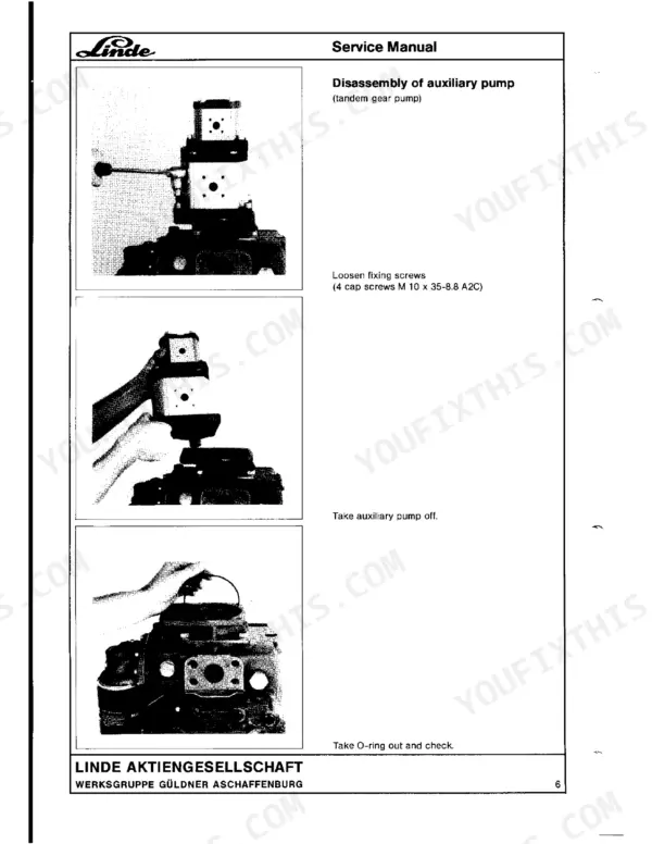
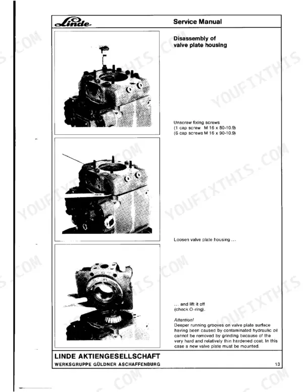
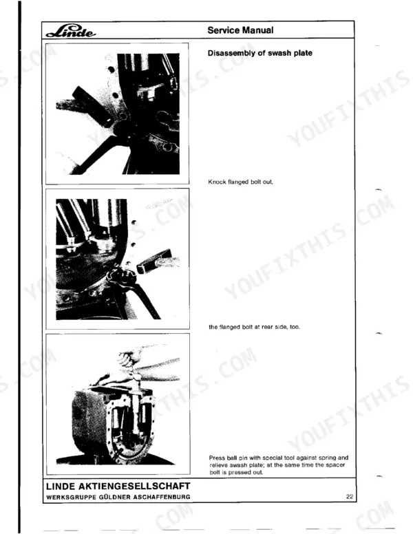
| Disassembly | 5-28 | Disassembly of Auxiliary Pump, Disassembly of Filter Flange, Disassembly of Valves, Disassembly of Valve Plate Housing, Disassembly of Control Cover, Disassembly of Pilot Valve |
| Determination of Axial Play | 29 | Drive Shaft |
| Drive Shaft Assembly | 29-34 | Front Taper Roller Bearing, Ball Race, Rear Taper Roller Bearing, Drive Shaft |
| Swash Plate Assembly | 35 | Flanged Bolt, Ball Pivot |
| Checking the Axial Play Between Retainer Plate and Holding Plate | 36-37 | Piston Assemblies, Collar Height, Retainer Plate, Holding Plate, Spacer Sheets |
| Control Cylinder Setting | 38-40 | Swash Plate, Control Piston, Needle Bearing Segments, Locking Pins |
| Retainer Determination | 41-46 | Piston, Mounting Aid, Cylinder Block, Support Disc, Locking Ring |
| Setting of Mechanical Neutral Position | 47 | Self-Securing Lock Nut, Adjusting Eccentric |
| Assembly of Control Cover | 48 | |
| Assembly of Valve Plate Housing and Valve Plate | 49-53 | Valve Plate Housing, Valve Plate, O-Rings, Spacer Bolts, High Pressure Relief Valve, Boost Pressure Valve |
| Assembly of Cartridge Filter | 54 | Cartridge Filter |
| Assembly of Auxiliary Pump | 55-60 | Auxiliary Pump, Pump Flange, Coupling Hub, PTO, Compression Spring, Locking Ring |
Quick Reference Specifications
| Specification | Value | Page |
|---|---|---|
| Pilot housing fixing screws torque | 86 Nm | p. 16 |
| Distance from dimension a to b | 0.1 ... 0.3 mm | p. 45 |
| Axial play between retainer plate and holding plate | 0.01 ... 0.03 mm | p. 38 |
| Axial play | 0.03 ... 0.05 mm | p. 32 |
| Swash plate angle | 18.5° ± 12' | p. 40 |
| Auxiliary pump fixing screws torque | 49 Nm | p. 57 |
| Control piston fixing screws torque | 49 Nm | p. 37 |
| Control cylinder piston bushing screw plug torque | 115 Nm | p. 40 |
| Valve plate housing fixing screws torque | 275 Nm | p. 51 |
| High pressure relief valve tightening torque | 120 Nm | p. 52 |
| Cartridge filter flange fixing screws torque | 25 Nm | p. 55 |
| Mechanical neutral position adjustment rewind | 0.4-0.5 mm | p. 40 |
Linde BPV 200 Common Problems This Manual Covers
Linde BPV 200 pump won't build pressure, loses drive under load on a warm machine
Check the high pressure relief valves first, then pull the valve plate housing and inspect the valve plate surface and cylinder block for scoring. Replace any scored rotating group parts. On reassembly, torque the valve plate housing fixing screws to 275 Nm and the high pressure relief valves to 120 Nm per page 52.
Manual Section: Assembly of Valve Plate Housing and Valve Plate p. 51Knocking or grinding noise from pump with rapid case overheating at full flow
Verify oil level and suction line restriction before you open anything. If noise stays, measure drive shaft axial play; page 32 calls for 0.03 to 0.05 mm. Inspect both taper roller bearings and the ball race for scoring, and shim the outer bearing ring back into spec during drive shaft assembly.
Manual Section: Drive Shaft Assembly p. 32Displacement control hunting, output surges and drops with steady input speed
Inspect the control piston and pilot housing for sticking and contamination in the control passages. Clean the passages, then set the swash plate angle to 18.5 degrees plus or minus 12 minutes during the control cylinder setting on page 38. Torque the control piston fixing screws to 49 Nm and the pilot housing screws to 86 Nm.
Manual Section: Control Cylinder Setting p. 38Metal flakes and bronze glitter found in the case drain filter element
Drain the case and cut the cartridge filter open to identify the debris. Tear the pump down through the retainer determination steps and measure the distance from dimension a to b; page 45 specifies 0.1 to 0.3 mm. Replace the piston assemblies and cylinder block together, never piecemeal.
Manual Section: Retainer Determination p. 45Oil weeping from the pump case split line and around the drive shaft seal
Clean the area and run the pump to confirm the leak source before condemning the shaft seal. Check drive shaft bearing play against the 0.03 to 0.05 mm axial play spec on page 32, since a loose shaft chews seals. Replace the O rings, apply fresh surface sealant at the control cover, and torque the cover fixing screws to 23 Nm.
Manual Section: Assembly of Control Cover p. 48Pump creeps or drifts in neutral, machine walks with the control lever centered
Verify the forked lever and control linkage return freely, then reset the mechanical neutral position on page 47. Loosen the self securing lock nut, turn the adjusting eccentric until creep stops, then rewind 0.4 to 0.5 mm (one third revolution) and lock the nut. Recheck at operating temperature.
Manual Section: Setting of Mechanical Neutral Position p. 47Frequently Asked Questions
What are the torque specs for the auxiliary pump fixing screws on a Linde BPV 200?
The fixing screws for the auxiliary pump (4 cap screws M 10 x 35-8.8 A2C) must be tightened to a torque of 49 Nm. p. 57
What is the torque specification for the valve plate housing fixing screws on a Linde BPV 200 variable hydraulic pump?
The valve plate housing is secured with one M 16 x 80-10.9 cap screw and six M 16 x 90-10.9 cap screws, which must be tightened to a torque of 275 Nm. p. 51
What is the required axial play for the retainer plate and holding plate?
The axial play between the retainer plate and the holding plate should be maintained between 0.01 mm and 0.03 mm. p. 38
What is the torque specification for the high pressure relief valve on a Linde BPV 200 variable hydraulic pump?
The high pressure relief valve should be tightened to a torque of 120 Nm. p. 52
How quickly can I access this manual after buying?
A 60-page Service Manual in searchable PDF format, available the moment you complete checkout. View on computer, tablet, or phone, with no shipping wait.
Is this Linde BPV 200 Service Manual printable?
Yes. Printing works from any reader and any printer, for your own shop use.

Reviews
There are no reviews yet.