
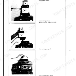
All 41 pages of this Linde HPV repair manual cover the complete axial piston pump family: HPV 55 ... 135-02, and the HPV...-02R variant. Inside, you get hydraulic schematics with full port identification (high-pressure, boost pump suction, control pressure supply, and drain), plus a full set of exploded views walking you through every sub-assembly from the rotating unit and valve plate housing down to the boost pump and servo control. Step-by-step procedures take you through complete disassembly, bearing adjustment, swash plate assembly, and M1, H1, and E1 control device mounting, with a dedicated tightening torques table covering standard and fine-pitch threads across property classes. Set cylinder barrel lift-off clearance to 0.1-0.3 mm; keep your mechanical zero position within 0.06 mm side-to-side or the pump will never track straight. Your machine is down. Get the numbers right the first time. Bookmarked by section so you can jump straight to bearing preload, shaft seal specs, or torque values without scrolling.
What's Inside This Linde HPV Series Repair Manual
| System | Pages | Key Topics |
|---|---|---|
| General Hints | 3 | Spare Parts Catalogue, Serial Number, Sealing Elements, Securing Elements, Seals, Tightening Torques |
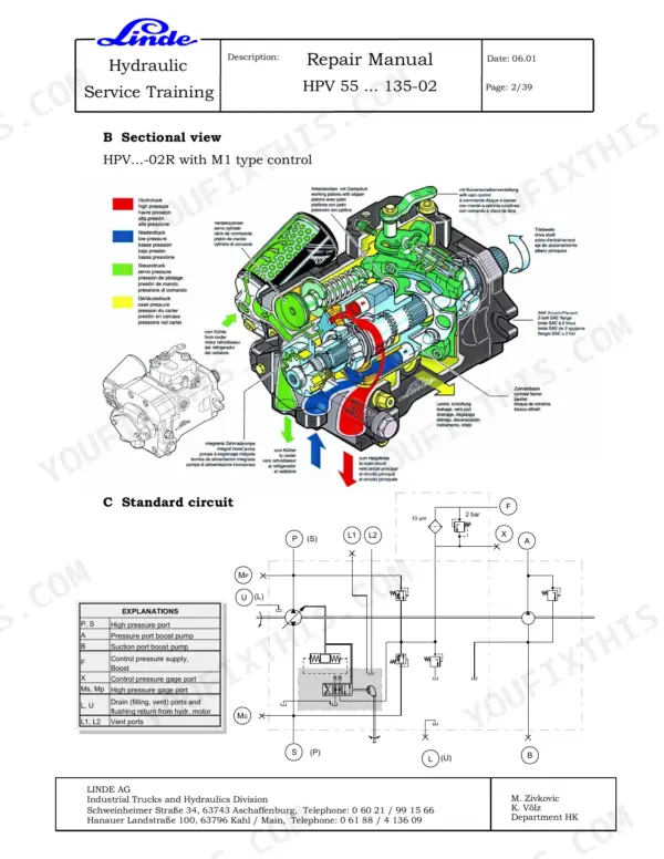
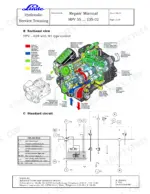
| Sectional View | 4 | High Pressure Port, Pressure Port Boost Pump, Suction Port Boost Pump, Control Pressure Supply, Control Pressure Gage Port, Drain Ports |
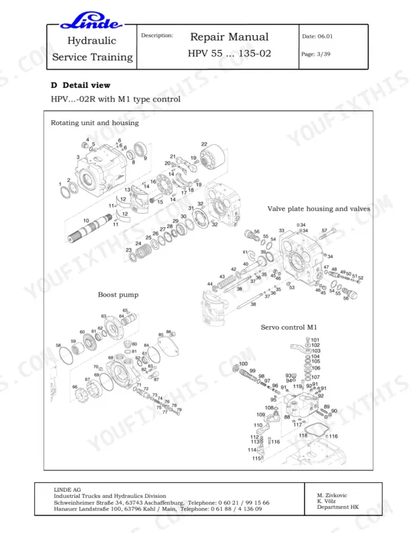
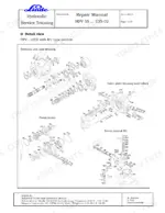
| Detail View | 5 | Rotating Unit, Valve Plate Housing, Valves, Boost Pump, Servo Control M1 |
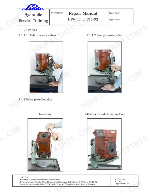
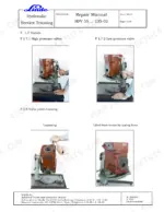
| Disassembly of Pump | 6-11 | Auxiliary Gear Pump, Strainer, Coupling Muff, Filter with Flange, Control M1, Spacer, Valves, Valve Plate Housing |
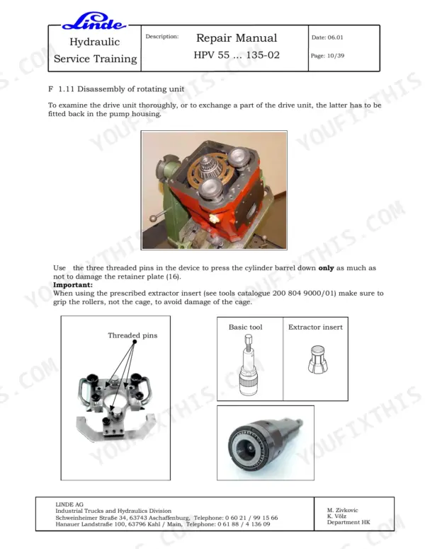
| Disassembly of Rotating Unit | 12-16 | Rotating Unit, Cylinder Barrel, Retainer Plate, Extractor Insert, Rollers, Cage, Bearing, Swash Plate Assembly |
| Assembly of Pump | 17 | Drive Shaft, Bearing, Running Ring |
| Adjusting the Axial Play of the Tapered Roller Bearing | 18-21 | Tapered Roller Bearing, Valve Plate Housing, Pump Housing, Shaft, Balancing Washers |
| Assembling the Swash Plate | 22-24 | Swash Plate, Holding Plate, Working Piston, Retainer Plate, Spacer Foil, Fixing Plate |
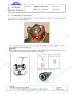
| Setting the Lift-Off Security of the Cylinder Barrel | 25-35 | Cylinder Barrel, Shaft, Pump Housing, Valve Plate, Swash Plate Assembly, Connecting Pipes, Control Piston, Shaft Seal |
| Mounting of Control Device | 36-40 | M1 Type Control, H1 Type Control, E1 Type Control |
| Tightening Torques Ma for Screws | 41 | Screw Surface Treatment, Liquid Glue Application, Standard Thread, Fine Pitch Thread, Screw Dimension, Property Classes |
Quick Reference Specifications
| Specification | Value | Page |
|---|---|---|
| All Models | ||
| Shaft seal replacement | Replace after every pump strip-down | p. 15 |
| Shaft seal sealant | Loctite 270 | p. 35 |
| Lift-off security clearance for cylinder barrel | 0.1 - 0.3 mm | p. 26 |
| Axial play of connecting pipes | 0.01 - 0.15 mm | p. 29 |
| HPV 55 ... 135-02 with M1 control | ||
| Spacer setting height X for M1 type control | 19.2 + 0.1 mm | p. 33 |
| HPV 55 ... 135-02 with H1, E1 control | ||
| Spacer setting height X for H1, E1 type control | 25.4 + 0.1 mm | p. 33 |
| HPV 55-02 | ||
| Tightening torque for HPV 55 high pressure valve (VD-9) | 60 Nm | p. 34 |
Linde HPV Series Common Problems This Manual Covers
Swashplate drifting or erratic servo response after reassembly
Check mechanical zero position first: set the pump so the housing parting face is level with the top of the washers or exceeds it by no more than 0.2 mm maximum, with no more than 0.06 mm difference between the two sides (page 31). Verify all Lube Tubes are correctly seated in the Hold-Down Cavity — a misplaced tube is the leading cause of erratic servo behavior. Confirm the spacer height X matches your control type before mounting the control device.
Manual Section: Checking and Setting Mechanical Zero Position p. 31Cylinder barrel lifting off valve plate, pump losing displacement and pressure
Measure lift-off security clearance after assembling the swash plate. Target clearance is 0.1 to 0.3 mm (page 26). Select shims to bring the measurement inside this range — too loose causes barrel lift under pressure, too tight causes binding. After shimming, recheck the figure with a dial indicator before closing the pump. Document the shim stack used for future reference.
Manual Section: Setting Lift-off Security of Cylinder Barrel p. 26Connecting pipes binding or knocking against hydrostatic bearing after pump rebuild
Check axial play of the connecting pipes to the hydrostatic bearing: acceptable range is 0.01 to 0.15 mm (page 29). Measure with a dial indicator while pressing the pipes axially in both directions. If play is outside range, adjust shims or inspect the bearing seat for damage. Binding pipes cause internal scoring; excessive play causes pressure loss and noise under load.
Manual Section: Setting Axial Play of Connecting Pipes p. 29High pressure valve leaking past seat after valve disassembly and reinstallation
Clean the valve seat and bore thoroughly before reinstallation. For the HPV 55-02, torque the high pressure valve (VD-9) to exactly 60 Nm (page 34). On other model sizes in this series, consult the tightening torques table on page 41 for the correct value — do not apply HPV 55-02 torque figures to larger displacement units. After torquing, pressure-test the circuit and verify no bypass across the valve seat.
Manual Section: Mounting Pressure Relief Valves p. 34Frequently Asked Questions
What are the replacement specifications for O-rings (sealing area)?
The manual recommends replacing all sealing and securing elements, including O-rings, during servicing. These seals are available in complete kits as spare parts. For instance, O-ring (36) and back-up ring (37) are mentioned for pre-assembly with connecting pipes (38). p. 3
What are the replacement specifications for Shaft seal?
The shaft seal (2) must be replaced after every pump strip-down. For installation, apply Loctite 270 sealant to the outside of the shaft seal ring (2) and use a protective sleeve and drive-in mandrel for precise positioning, then let the securing ring (1) snap in. p. 15
How do you fix linde HPV pump housing leaking sealant at rear head interface after rebuild?
Remove the rear head and strip all old sealant completely from the sealing area. Deburr every edge before reapplying — skipping this step is the most common cause of repeat leaks. Apply fresh Linde-approved sealant evenly, reassemble, and torque all fasteners per the class and surface treatment table on page 41. Inspect O-rings and replace any that show compression set or cracking. p. 3
How do you fix shaft seal weeping fluid after disassembly and reassembly?
Replace the shaft seal every time you strip the pump — do not reuse the old one regardless of appearance (page 15). Apply Loctite 270 to the seal bore on installation (page 35). Press the seal squarely to seat depth, verify it sits flush without cocking, then check the drain port is clear so pressure cannot build behind the seal and blow it out early. p. 15
How will I receive this Linde HPV 55 ... 135-02 & variants Repair Manual?
Immediate download of the complete 41-page searchable Repair Manual. Access it on any device, from a laptop at your desk to a phone in the field.
Can I print specific sections of this Linde HPV 55 ... 135-02 & variants Repair Manual?
Yes. Print the pages or sections you need for your own shop use. Any standard printer works.
Does this Linde HPV 55 ... 135-02 & variants manual include hydraulic schematics?
Included. Hydraulic system schematics cover all circuits, control valves, and component specifications for the Linde HPV 55 ... 135-02 & variants.

Reviews
There are no reviews yet.