
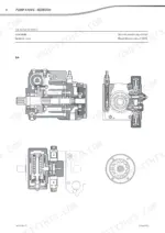
Within the hour you could have an A10VG clamped on the bench with its boost pump cover off, and this Rexroth A10VG service manual PDF is the 54-page factory repair manual (OEM ID 647255EN-DE) for that hydraulic pump. Sectional views open the book and trace the pressure cut-off, control unit, rotary group and positioning piston, so you know what sits behind each fastener before you touch it. The procedures that follow cover sealing the drive shaft, boost pump and valves, pulling the rotary group, fitting the Turcon-Glyd-ring and servicing the HW, DA, HD and EP control units. A good share of the back of the book goes to adjustment: mechanical and hydraulic zero position, high pressure valves and pressure cut-off. Set boost pressure to 18 bar nominal, with a 40 bar peak, and tighten the pole tube to 19 Nm. It's just you, a bare housing and nobody to ring. Bookmarked, text-searchable and bought once, it stays yours for as long as this pump runs.
What's Inside This Rexroth A10VG Manual
| System | Pages | Key Topics |
|---|---|---|
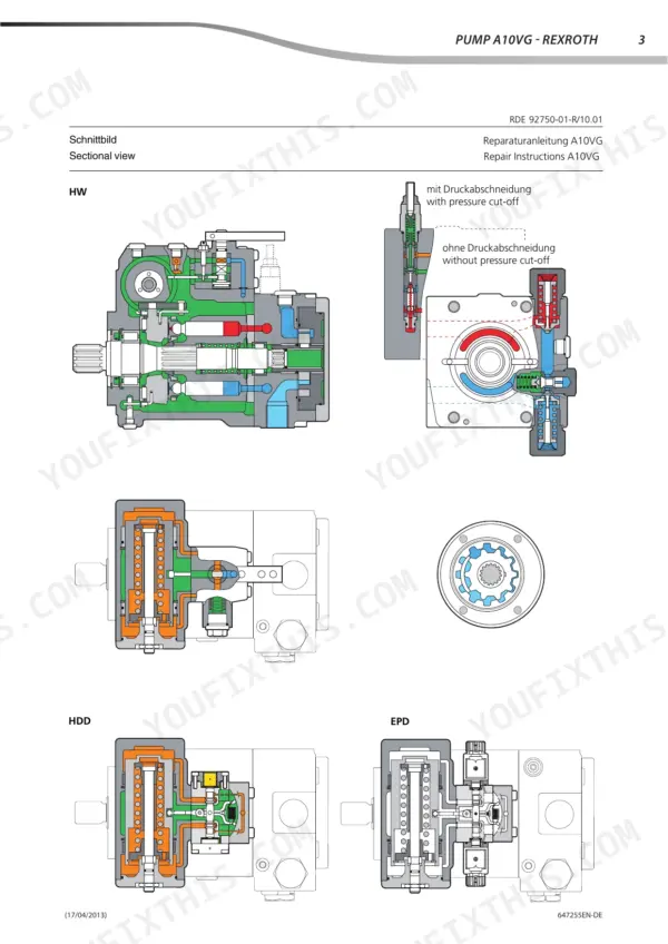
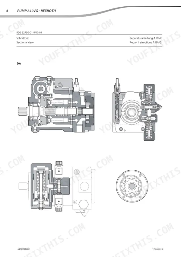
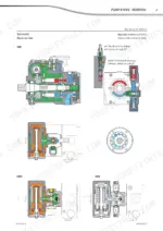
| Sectional View | 5-6 | Pressure Cut-Off, Control Unit, Rotary Group, Positioning Piston |
| General Repair Instructions | 7 | |
| Seal Kits and Sub Assembly Groups | 8-10 | Drive Shaft, Peripheral Seal Kit, Rotary Group, Positioning Piston, Connection Plate, Control Unit, Boost Pump, High Pressure Valve |
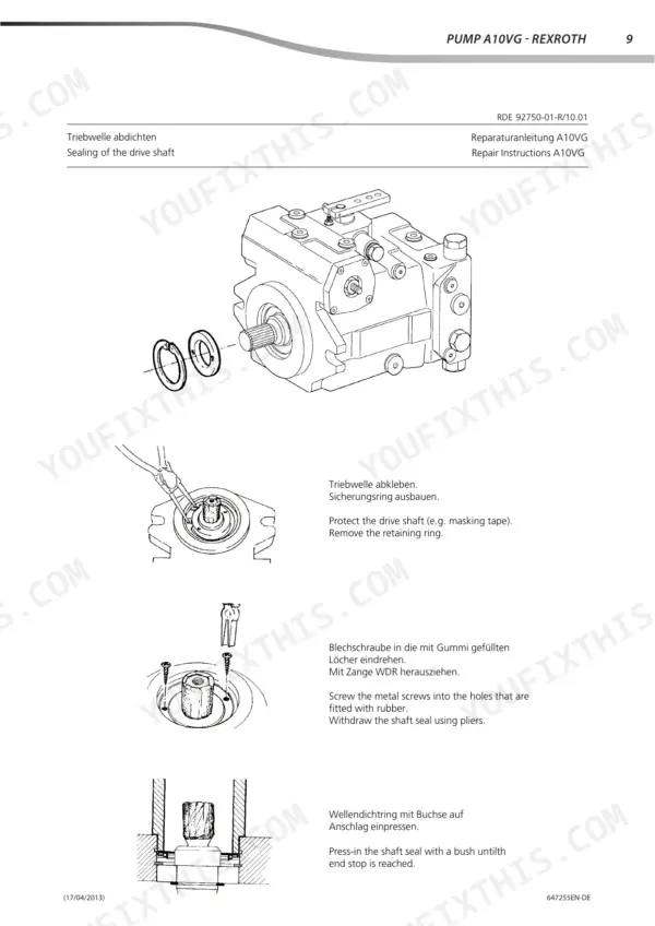
| Sealing of the Drive Shaft | 11 | |
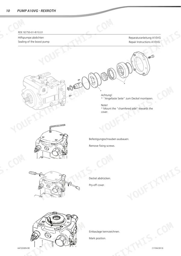
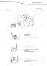
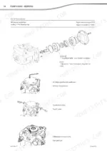
| Sealing of the Boost Pump | 12-14 | Fixing Screws, Cover, O-Ring, Wear Plate, Locating Pin, Kantsil-Ring, Unloading Channel |
| Sealing of the Control Piston Cover | 15 | O-Ring, Housing |
| Sealing of the Valves | 16 | O-Rings, Bypass Function, Support Ring |
| Sealing of the Pressure Cut-Off Valve | 17 | Sealing Nut, Adjustment Dimension, Valve Setting |
| Sealing of the Regulator Valve | 18 | Control Valve |
| Removal of the Control Unit | 19 | Fixing Screws, Control Unit, Sealing Surface |
| Control Units | 20-24 | HW Control Unit, DA Control Unit, HD Control Unit, EP Control Unit, Proportional Solenoids |
| Pump Disassembly | 25-27 | Boost Pump, Connection Plate, Control Plate, Rotary Group, Eccentric Screw, Cylinder |
| Removal of the Rotary Group | 28 | Drive Shaft, Bearing Shells, Spring |
| Disassembly of the Positioning Piston | 29-30 | Control Unit, Control Piston, Housing, Bush, Turcon-Glyd-ring |
| Inspection Notes | 31-33 | Bearings, Splines, Running Surfaces, Control Piston, Cylinder Bores, Control Plate |
| Turcon-Glyd-Ring | 34 | Housing |
| Assembly of the Pump | 35-37 | Bearing Shells, Positioning Piston, Swash Plate, Boost Pump, Control Device |
| Installation of the Rotary Group | 38-41 | Drive Shaft, Bearings, Pressure Pins, Piston, Retaining Plate, Cylinder |
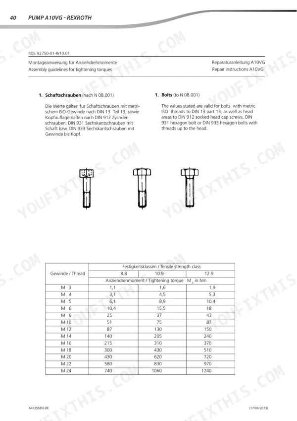
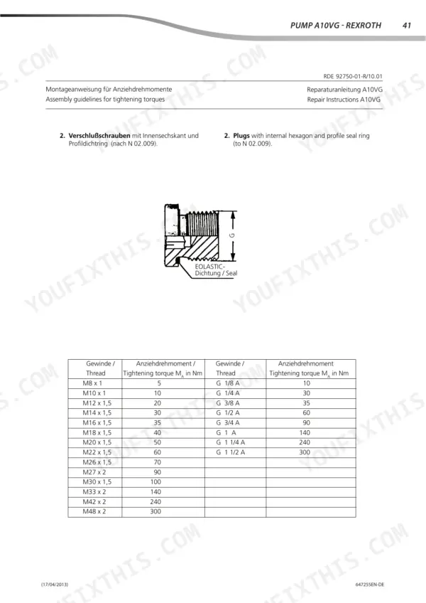
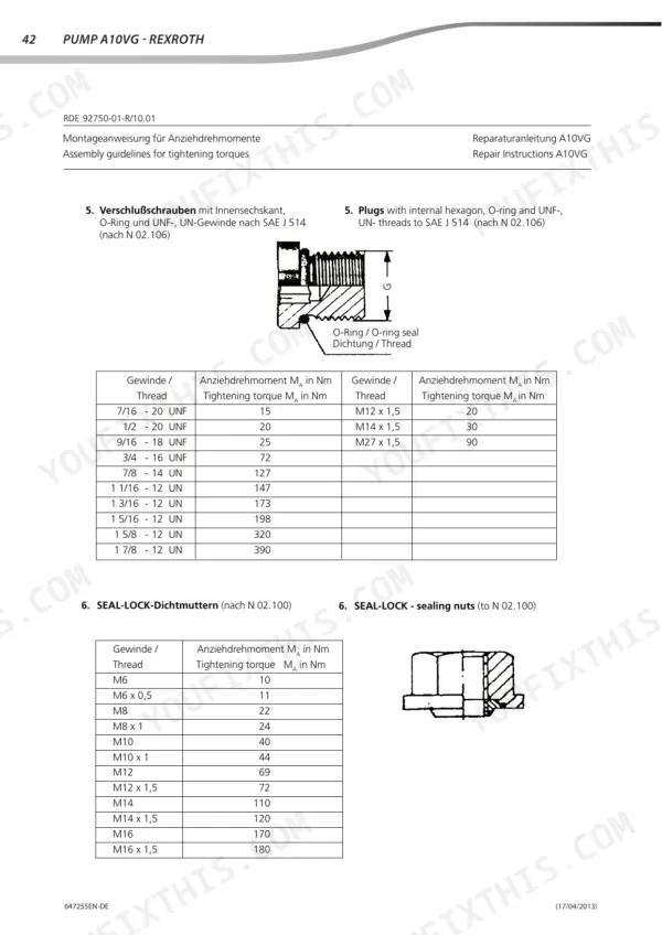
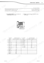
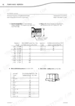
| Assembly Guidelines for Tightening Torques | 42-45 | Bolts, Plugs, Sealing Nuts, Orifices |
| Safety Regulations | 46-47 | General Advice, Starting, Hydraulic Equipment, Exhaust Gas, Flexible Hoses |
| Adjustment Instructions | 48-54 | Mechanical Zero Position, Hydraulic Zero Position, Boost Pressure, High Pressure Valves, Pressure Cut-Off, Bypass Valve |
Quick Reference Specifications
| Specification | Value | Page |
|---|---|---|
| Bleed screw torque | 1 Nm | p. 22 |
| Plastic nut with rubber coating torque | 5+1 Nm | p. 24 |
| Boost pressure nominal pressure | 18 bar | p. 50 |
| Boost pressure nominal pressure (pH) | 18 bar | p. 50 |
| Boost pressure peak pressure | 40 bar | p. 50 |
| Boost pressure peak pressure (pH) | 40 bar | p. 50 |
| Pole tube tightening torque | 19 Nm | p. 24 |
| Clamping screw tightening torque | 6.1 Nm | p. 24 |
| DA control start of control pressure | 40-50 bar | p. 53 |
| M6 orifice tightening torque (new) | 3 Nm | p. 45 |
| Max. towing speed | 2 km/h | p. 52 |
| Max. towing distance | 1 km | p. 52 |
Rexroth A10VG Common Problems This Manual Covers
Rexroth A10VG boost pressure reading at gauge port G not matching the nominal setting
Depressurise the system and lower the working elements before fitting gauges, per page 47. Connect a pressure gauge to port G and bring the pump to operating temperature, because readjustment is only allowed when hot. Set nominal boost pressure to 18 bar and check peak pressure of 40 bar at max speed following page 50. Final values follow the works order.
Manual Section: Adjustment Instructions p. 50Drive shaft seal leaking oil at the shaft end of the pump housing
Depressurise the system and use proper aids when hunting the leak, since oil escaping under high pressure can penetrate skin (page 47). Mask the drive shaft with tape, remove the retaining ring, screw metal screws into the rubber-filled holes and pull the seal with pliers following page 11. Press the new seal in with a bush to the end stop. Inspect the shaft for seal grooves per page 31.
Manual Section: Sealing of the Drive Shaft p. 11Mechanical zero position out of adjustment, gauges at MA and MB showing unequal pressure
Depressurise the system and lower the working elements before connecting gauges (page 47). Connect both control chambers with a nominal size 6 hose so no residual signal comes from hydraulic zero, then fit gauges to MA and MB. Adjust zero following page 48 until both gauges read the same pressure with the drive blocked, and find the dead band. Recheck after any control piston cover reseal, per page 15.
Manual Section: Adjustment Instructions p. 48Hydraulic zero position off, gauges at X1 and X2 reading unequal pressure with drive blocked
Depressurise the system and lower the working elements before fitting or removing gauges, per page 47. Connect pressure gauges to X1 and X2 and adjust the eccentric until both read the same pressure with the drive blocked, following page 49. Never turn the eccentric more than 90 degrees in either direction.
Manual Section: Adjustment Instructions p. 49Pressure cut-off and high pressure valve settings incorrect after resealing the pressure cut-off valve
Measure and record the adjustment dimension before swapping the sealing nut (page 17), then check the valve setting after assembly. With gauges on MA and MB at operating temperature, block the cut-off by turning its adjustment screw to the stop at max 2 Nm while depressurised, following page 51. Run briefly over the HP valves, then reset the cut-off; HP valves sit 10% higher.
Manual Section: Sealing of the Pressure Cut-Off Valve p. 17Rotary group pistons with axial play or scored cylinder sliding surface found at teardown
Inspect piston sliding surfaces for scratches, metal deposits and axial play, and replace pistons only as a set, following page 32. Check the cylinder sliding surface and control plate for grooves or embedded particles; replace those as a set too, per page 33. Replace all bearings and check the control piston guide bush for wear (page 31).
Manual Section: Inspection Notes p. 32Frequently Asked Questions
How do I adjust the Rexroth A10VG high-pressure relief valve?
To adjust the high-pressure valves, connect pressure gauges to MA and MB. Operate the valves with a small pump flow. The HP valves must be adjusted to a value 10% higher than the pressure cut-off. Ensure readjustment is only performed at operating temperature. p. 51
How do I set the Rexroth A10VG mechanical zero stroke?
Connect both control chambers with a nominal size 6 hose to avoid residual signals. Connect pressure gauges to MA and MB. Adjust the zero position so that with a blocked drive, both pressure gauges indicate the same pressure value. p. 48
What are the tightening torque specifications for M10 bolts on the Rexroth A10VG?
For M10 bolts, the tightening torque depends on the tensile strength class: 51 Nm for class 8.8, 75 Nm for class 10.9, and 87 Nm for class 12.9. p. 42
What is the maximum towing speed for a vehicle with an A10VG pump?
The maximum towing speed should not exceed 2 km/h. Higher speeds depend on the hydraulic motor speed or the selected gear. p. 52
What is the boost pressure setting for the A10VG pump?
The nominal boost pressure (pH) is 18 bar, with a peak pressure of 40 bar at maximum speed. Readjustment should only be performed at operating temperature. p. 50
What format is this Rexroth A10VG manual in?
Instant PDF download. You get the full 54-page searchable Service Manual immediately after payment. Open it on your laptop, tablet, or phone right in the shop.
Is this Rexroth A10VG Service Manual printable?
Yes. Print the sections you need to take out to the shop for your own use. Standard letter or A4 paper works.

Reviews
There are no reviews yet.