
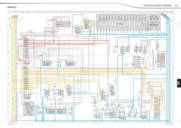
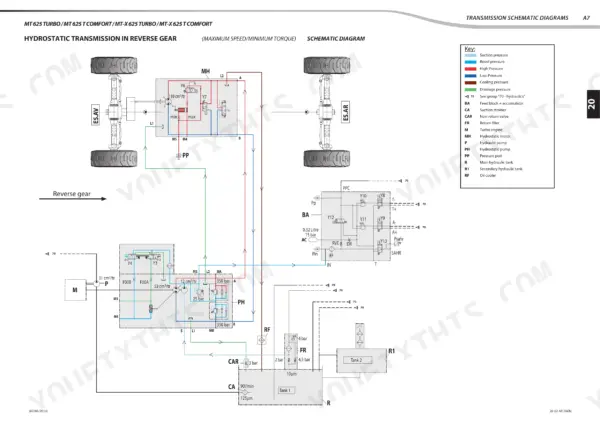

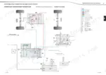
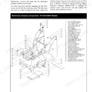
Manitou repair manual 647230EN takes the 625 telehandler series apart across 467 pages, covering six variants from the MT 625 Turbo to the MLT-X 625-75 H. Electrical work fills the largest share of this Manitou MLT 625-75 H repair manual PDF, with schematic diagrams tracing each harness circuit and fault code tables that let you pin down a dead sensor or relay before you start pulling connectors. Hydraulic schematics map oil flow from the pump out to the boom rams, and separate chapters handle engine removal and refit, transmission adjustment, brakes, full boom removal and refit, and cab troubleshooting. Check the system against its 310 bar maximum pressure and 90 L/min flow rate, then torque the rear axle mounting screws to 590 N.m ± 10%. A parked telehandler costs you lifts every hour. Bookmarked by chapter and text-searchable, this PDF is a one-time purchase that stays yours for the life of the machine.
What's Inside This Manitou MT 625 T to MLT-X 625-75 H Repair Manual
| System | Pages | Key Topics |
|---|---|---|
| General Instructions and Safety Notice | 4-27 | General Characteristics and Safety, Rules for Maintenance |
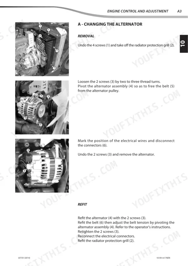
| Engine | 28-95 | Engine Components Location, Engine Control and Adjustment, Engine Removal, Engine Refit |
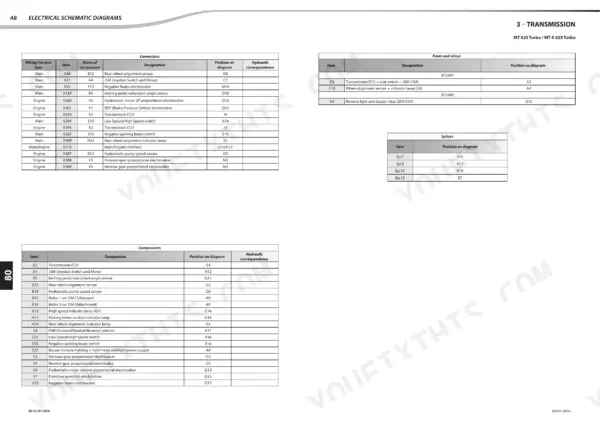
| Transmission | 96-129 | Transmission Schematic Diagrams, Transmission Components Location, Transmission Control and Adjustment |
| Axle Assembly - Axle | 130-131 | Axle |
| Brake | 132-147 | Brake Characteristics and Specifications, Brake Control and Adjustment |
| Telescopic Boom | 148-181 | Boom Characteristics and Specifications, Boom Components Location, Boom Control and Adjustment, Boom Removal, Boom Refit |
| Hydraulic | 182-251 | Hydraulic Characteristics and Specifications, Hydraulic Schematic Diagrams, Hydraulic Components Location, Hydraulic Control and Adjustment, Hydraulic Components Removal |
| Electricity | 252-425 | Electrical Characteristics and Specifications, Electrical Schematic Diagrams, Electrical Components Location, Electrical Control and Adjustment, Electrical Components Refit |
| Driver Cab | 426-467 | Driver Cab Characteristics and Specifications, Driver Cab Removal, Driver Cab Troubleshooting |
Quick Reference Specifications
| Specification | Value | Page |
|---|---|---|
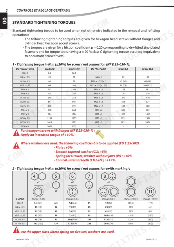
| Universal joint torque | 37 N.m ± 10% | p. 125 |
| Hydrostatic pump mounting screw torque | 175 N.m ± 10% | p. 125 |
| Maximum pressure | 310 bar | p. 186 |
| Maximum flowrate | 90 L/min | p. 186 |
| Kubota V3307 DI-T (Turbo) engine - min rpm | 895 ±25 rpm | p. 212 |
| Kubota V3307 DI-T (Turbo) engine - nominal rpm loaded | 2600 rpm | p. 212 |
| Hydraulic pump mounting screw torque | 17.5 daN.m ±10% | p. 246 |
| F4 fuse rating | 10A | p. 258 |
| F6 fuse rating | 10A | p. 258 |
| Fuel Tank Capacity | 63L | p. 19 |
| Engine Oil Capacity | 11.2L | p. 19 |
| Cooling Circuit Capacity | 12L | p. 19 |
Manitou MT 625 T to MLT-X 625-75 H Common Problems This Manual Covers
Manitou MT 625 Y12 hydraulic cut-off electrovalve fault with boom and attachment hydraulic functions not responding
Test the Y12 hydraulic cut-off electrovalve (VS) at its connector using the electrovalve values on page 319. Confirm a 12 V supply at the plug, then disconnect it and measure coil resistance against 8 Ω. Current draw should sit near 1.5 A. If the coil reads open or shorted, replace the electrovalve before you start chasing the pump.
Manual Section: Electricity p. 319Y14 and Y18 lifting and lowering proportional cut-off electrovalves fault with boom not lifting or lowering
Measure coil resistance on the Y14 and Y18 lifting and lowering proportional cut-off electrovalves using the values on page 320. With the connector unplugged, check resistance against 5.2 Ω. Plug it back in and confirm a 12 V supply and roughly 1.5 A draw. A dead coil or missing supply points to the valve or its wiring.
Manual Section: Electricity p. 320Y13 negative brake electrovalve electrical fault with negative brake not releasing
Unplug the Y13 negative brake electrovalve and measure coil resistance against 8 Ω, using the electrovalve specs on page 319. Reconnect it and verify a 12 V supply at the connector with about 1.5 A draw when commanded. If the coil tests good and supply is present, go to the Brake section starting on page 132.
Manual Section: Electricity p. 319Y19 fan speed and Y20 fan direction electrovalves fault with cooling fan speed or reversing not working
Check the Y19 fan speed electrovalve against page 321: a 10 V to 14 V supply, current varying from 0 mA to 1200 mA, and 7.1 Ω coil resistance. Then test the Y20 fan direction electrovalve using page 322 for a 10 V to 14 V supply, 1.5 A to 2.5 A draw, and 7.1 Ω resistance.
Manual Section: Electricity p. 321Dashboard showing a stored ECU error code with machine functions not responding
Check the code shown on the dashboard against the error code reference on pages 416 and 417 before you swap any parts. Verify the fault using the ECU diagnostics in the Electrical Troubleshooting section. Then trace the related circuit on the wiring diagrams starting before you condemn the ECU or replace any electrovalve.
Manual Section: Electrical TroubleshootingKubota V3307 DI-T turbo engine idle speed or maximum unladen rpm out of specification
Measure engine speed with a tachometer at idle and compare it against 895 ±25 rpm, listed on page 212. Then check maximum unladen speed against 2800 rpm and nominal loaded speed against 2600 rpm. Get engine speed back within these figures before you judge hydraulic performance, because low rpm makes every boom function feel slow.
Manual Section: Hydraulic p. 212Frequently Asked Questions
What does error code 520410 mean on a Manitou MT 625 T Comfort?
Error code 520410 indicates a 'Man-Frame Interface fault' where the LED 16 is lit. The recommended repair action is to replace the dashboard module. p. 416
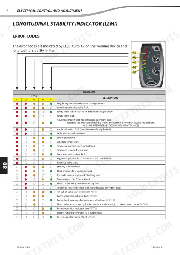
How do I reset the longitudinal stability limiter on a Manitou MTX 625?
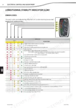
If the error code for gauge calibration fault appears, resetting the longitudinal stability limiter and warning device may resolve the problem. This is classified as an occasional maintenance task (G). p. 395
What is the tightening torque for the crankshaft pulley fastening screw on a Manitou MT 625 T?
The tightening torque for the crankshaft pulley fastening screw is between 255 and 274 N.m. p. 41
What is the capacity of the hydraulic oil tank for the MT 625 Turbo?
The hydraulic oil tank capacity for the MT 625 Turbo is 115 liters. p. 19
What is the correct tightening torque for the distributor coupling 1A on a Manitou MT 625 T?
The correct tightening torque for the distributor coupling 1A is 100 N.m (+/- 15%). p. 235
How quickly can I access this Manitou MT 625 Turbo manual after buying?
This is a 467-page searchable PDF ready for immediate download. Works on any device, so pull it up on your phone while you're under the hood. No shipping, no waiting.
Am I able to print pages from this Manitou MT 625 Turbo manual?
Print away. There is no DRM and no page limit. Many buyers print one chapter at a time and leave the rest on a tablet.


Reviews
There are no reviews yet.