
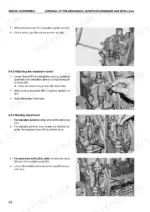
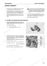
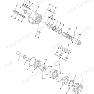
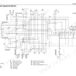
The 170-page Same Deutz-fahr Serie 1000 shop manual PDF settles what no secondhand source can: the factory clearances, protrusions and timing angles for your 1000.3, 1000.4 and 1000.6 engines in three, four and six cylinders. Governor work runs deep here, from separating the mechanical governor housings through L.D.A. valve bench adjustment, hunting and idle settings, and a technical data section filling close to a quarter of the book lists piston, ring, crankshaft and camshaft dimensions by part code and cylinder count. Reassembly ends with head gasket thickness calculation, injection pump timing, valve clearance adjustment and a start-up test with pump synchronizing. Set naturally aspirated injectors to open at 180 +8 bar, then take the head bolts to 50 Nm (37 lb.ft.) before the final 100 ±3° turn. A guessed head torque comes back as a blown gasket. The file is bookmarked and text-searchable and carries the piston codes, so you order the right pistons and rings the first time, before the block goes back together.
What's Inside This Same Deutz-fahr SERIE 1000, SERIE 1000/3-4-6 cylinders Manual
| System | Pages | Key Topics |
|---|---|---|
| Important Preliminary Information | 5-6 | Safety and Accident Prevention, Engine Removal, Engine Stand Mounting, Engine Cleaning, Engine Type Codes |
| How to Consult and Use the Manual | 7-9 | Removal and Refitting of Assembled Units, List of Special Tools, Tightening Torques, Updating the Manual, Inserting Updates, Supplementary Pages, Updated Pages, Symbols Used, Wire Ropes, Polyester Slings |
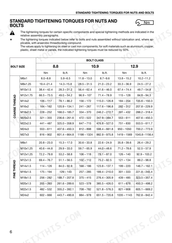
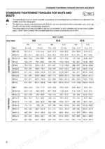
| Standard Tightening Torques, Threadlockers and Sealants | 10-12 | Coarse Thread Bolts, Fine Thread Bolts, Bolt Class 8.8, Bolt Class 10.9, Bolt Class 12.9, Threadlockers, Degreasers and Activators, Sealants, Instant Adhesives, Silicone Sealants, Polyurethane Sealants, Retaining Compounds, Lubricants |
| Special Tools and Conversion Factors | 13-14 | Valve Spring Compressor, Bore Gauge, Governor Disassembly Tool, Sleeve Protrusion Tool, British to Metric Units, Metric to British Units |
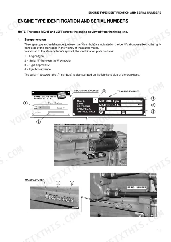
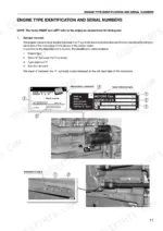
| Engine Type Identification, Injectors and Advance Angle | 15-18 | Identification Plate, Engine Type, Serial Number, Type Approval Number, Injection Advance Angle, EPA Class Designation, Injection Pump, Pump Identification Plate, Engine Data Plate, Camshaft Markings |
| Preliminary Removal Operations, Cooling and Intake Pipes | 19-23 | Starter Motor, Flywheel Retaining Flange, Cooling and Intake Pipes, Air Intakes |
| Removal of the Cylinder Heads, Thermostats and Coolant Pump | 24-36 | Dismantling the Cylinder Heads, Dismantling the Rocker Arm Supports, Testing the Thermostats, 3- and 4-Cylinder Versions, 6-Cylinder Versions |
| Removal of the Unit Pumps, Actuator and Governor Drive | 37-47 | Fuel Filter, Fuel Lift Pump, Injection Pumps, High-Pressure Pipes, Mechanical Governor, Electronic Actuator, Assembly |
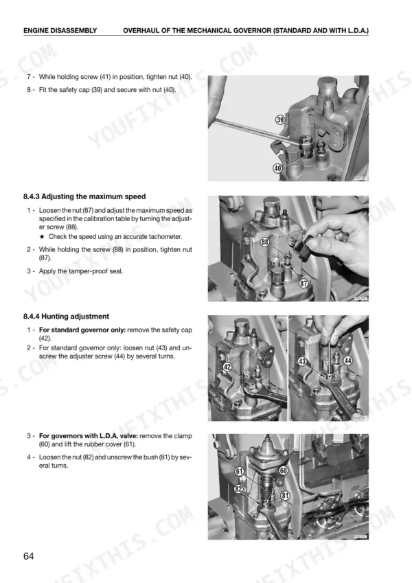
| Overhaul of the Mechanical Governor | 48-69 | Disassembly of the Standard Governor, Separation of the Lower and Upper Housings, Assembly of the Lower Housing, Adjusting the Height of the Lever Control Bush |
| Adjustment of the Electronic Actuator, Control Rod and Heat Exchanger | 70-73 | Calibration of Electronic Actuators, Heat Exchanger Assembly, Oil Cooler Assembly, Gasket |
| Dismantling the Valve Timing Drive and Crankshaft | 74-84 | Engine Speed Pick-Up, Crankshaft Pulley, Pulse Wheel, Timing Cover, Timing Gear, Camshaft, Removal of the Harmonic Balancer, Overhaul of the Harmonic Balancer |
| Removal of the Pistons, Cylinder Liners and Rear Oil Seal | 85-87 | Separating the Piston-Connecting Rod Assembly, Oil Seal, Cover, Carrier |
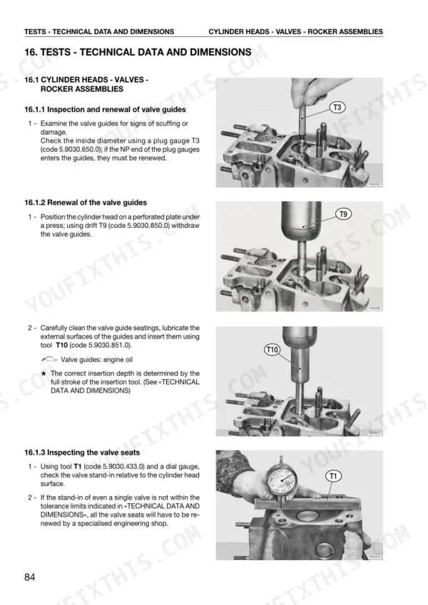
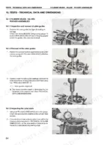
| Tests - Technical Data and Dimensions | 88-126 | Cylinder Heads - Valves - Rocker Assemblies, Inspection and Renewal of Valve Guides, Renewal of the Valve Guides, Inspecting the Valve Seats |
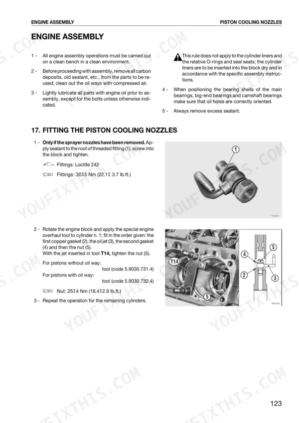
| Fitting the Piston Cooling Nozzles, Pistons, Crankshaft and Sump | 127-137 | Fitting the Piston Cooling Nozzles, Fitting the Cylinder Liners, Pistons and Connecting Rods, Cylinder Liner, O-Rings, Piston Rings, Expander, Oil Scraper Ring, Gudgeon Pin, Connecting Rod, Clamping Blocks, Fitting the Camshaft-Crankshaft and Connecting Rod Big-Ends, Oil Pump, Head Gaskets |
| Refitting the Cylinder Heads, Valve Timing and Injection Pumps | 138-152 | Injection Pump Control Rod, Timing Gears, Timing the Injection Pumps, Rocker Assemblies, Valve Clearances |
| Final Engine Assembly Operations | 153-167 | Flywheel Housing Flange, Rear Oil Seal Carrier |
| Engine Tests | 168-170 | Initial Start-Up and Oil Pressure Check, Synchronizing the Injection Pumps, Angular Adjustment of the Injection Pumps |
Quick Reference Specifications
| Specification | Value | Page |
|---|---|---|
| Injector nut torque | 39 Nm (28.8 lb.ft.) | p. 90 |
| Injection pump full stroke | 19 mm (0.749 in.) | p. 94 |
| Injection pump retaining nuts torque (initial) | 5 Nm (3.68 lb.ft.) | p. 146 |
| Injector protrusion | 2.383 - 3.095 mm (0.094 - 0.122 in.) | p. 88 |
| Cylinder head bolt torque | Stage 1: 50 Nm (37 lb.ft.), Final: 100 ±3° | p. 134 |
| 3- and 4-cylinder rocker cover bolt torque | 5 Nm (3.7 lb.ft.) | p. 148 |
| Tightening torque M6x1 (8.8 class) | 8.0-8.8 Nm | p. 10 |
| Tightening torque M24x2 (12.9 class) | 1035-1143 Nm | p. 10 |
| Valve stand-in (Inlet) | 0.7-1.3 mm | p. 92 |
| Valve stand-in (Exhaust) | 0.9-1.5 mm | p. 92 |
| Valve stem diameter (Inlet) | 8.972-8.987 mm | p. 93 |
| Valve stem diameter (Exhaust) | 8.980-8.987 mm | p. 93 |
Same Deutz-fahr SERIE 1000, SERIE 1000/3-4-6 cylinders Common Problems This Manual Covers
Same Deutz-fahr Serie 1000 engine inlet and exhaust valve clearance out of specification on rocker check
Measure inlet and exhaust valve clearance and set both to 0.15-0.25 mm using the table on page 94. Inspect the rocker assemblies for wear while the cover is off, then torque 3- and 4-cylinder rocker cover bolts to 5 Nm (3.7 lb.ft.) as listed on page 148.
Manual Section: Tests - Technical Data and Dimensions p. 94Cylinder head inlet and exhaust valve stand-in beyond limit when inspecting valve seats and guides
Measure valve stand-in with the valve stand-in tool listed on page 13: inlet must read 0.7-1.3 mm and exhaust 0.9-1.5 mm per page 92. Check stem diameter against 8.972-8.987 mm inlet and 8.980-8.987 mm exhaust on page 93, then inspect guides and seats before you commit to renewal.
Manual Section: Tests - Technical Data and Dimensions p. 92Naturally aspirated engine injector nozzle opening below calibration pressure during injector testing
Test each injector on naturally aspirated engines against the 180 +8 bar (2610.5 +116 psi) calibration pressure listed on page 96. Measure injector protrusion against 2.383-3.095 mm (0.094-0.122 in.) using the data on page 88, then torque the injector nut to 39 Nm (28.8 lb.ft.) per page 90.
Manual Section: Tests - Technical Data and Dimensions p. 96Cylinder head bolts needing correct stage torque and angle-tightening on refit after head removal
Torque the cylinder head bolts in two stages as page 134 specifies: 50 Nm (37 lb.ft.) for Stage 1, then a final angle-tightening of 100° ±3°. Mark each bolt head before the angle pass so you can see the turn. Recheck valve clearance at 0.15-0.25 mm once the heads are down.
Manual Section: Engine Assembly p. 134Unit injection pumps out of synchronization after refitting pumps and high-pressure pipes
Torque the injection pump retaining nuts in stages: 5 Nm (3.68 lb.ft.) initial on page 146, 10 Nm (7.37 lb.ft.) for Stage 1 on page 142, then 16 ± 4 Nm (11.8 ± 3 lb.ft.) for Stage 2 on page 144. Verify the injection advance angle on the data plate (page 18), then synchronize the pumps at start-up.
Manual Section: Engine Assembly p. 144Mechanical governor drive reassembled on the bench with backlash out of adjustment
Adjust governor drive backlash during reassembly following the overhaul procedure on page 42. Then rebuild the governor itself from page 48: separate the lower and upper housings with the governor disassembly tool listed on page 13, set the lever control bush height and L.D.A. valve, and finish with the final adjustments.
Manual Section: Overhaul of the Mechanical Governor Drive p. 42Frequently Asked Questions
What are the torque specifications for the cylinder head bolts on the Serie 1000 engine?
The cylinder head bolts are tightened in two stages. First, tighten the bolts to 50 Nm (37 lb.ft.) following the indicated sequence. Then, perform a final angle-tightening of 100° ± 3° using a protractor. p. 138
What is the specified valve clearance for the Serie 1000 engine?
The valve clearance for both inlet and exhaust valves is 0.20 ± 0.05 mm (0.008 ± 0.002 in.). This adjustment must be performed with the piston at TDC at the beginning of its power stroke. p. 152
What is the correct main bearing cap bolt torque on the Same Deutz-fahr SERIE 1000, SERIE 1000/3-4-6 cylinders?
The main bearing cap bolts are tightened in three steps. First, tighten to 10 Nm (7.4 lb.ft.), then to 40 Nm (29.5 lb.ft.), and finally angle-tighten an additional 55° ± 1°. p. 132
What is the tightening torque for the big-end cap bolts on the SAME Deutz-Fahr Serie 1000 engine?
The big-end cap bolts are tightened in two stages. First, tighten to 10 Nm (7.4 lb.ft.), then to 30 Nm (22.1 lb.ft.), followed by a final angle-tightening of 90° ± 1°. p. 133
What is the pressure relief valve calibration for the 6-cylinder oil pump on the SAME Deutz-Fahr Serie 1000 engine?
The pressure relief valve for the 6-cylinder oil pump is calibrated to 5 ± 0.5 bar (72.5 ± 7.25 psi). p. 84
Do I get instant access to this Same Deutz-fahr Serie 1000 Shop Manual?
A single searchable PDF file of 170 pages, downloadable right after payment. Nothing ships, nothing waits in the mail.
Am I able to print pages from this Same Deutz-fahr Serie 1000 manual?
Yes. Print the pages you need for the job in your own shop, and bin them when they get greasy.

Reviews
There are no reviews yet.