
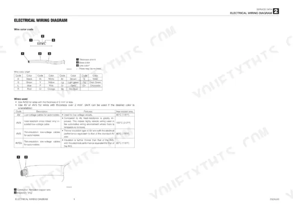
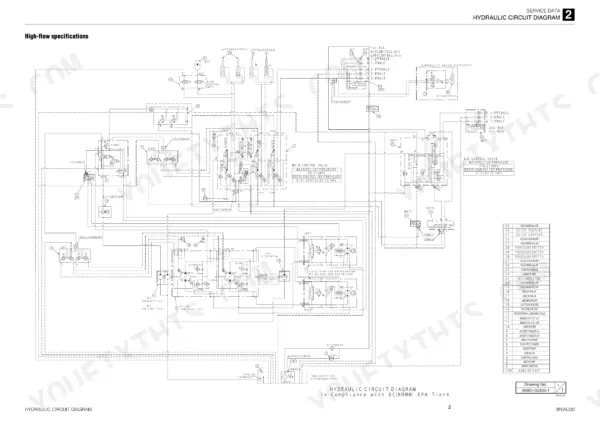
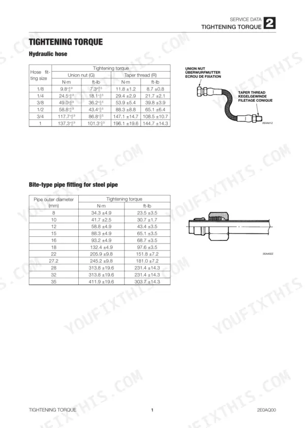
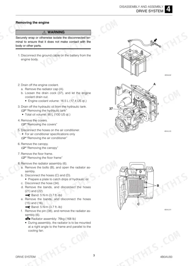
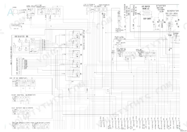
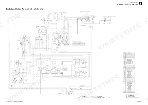
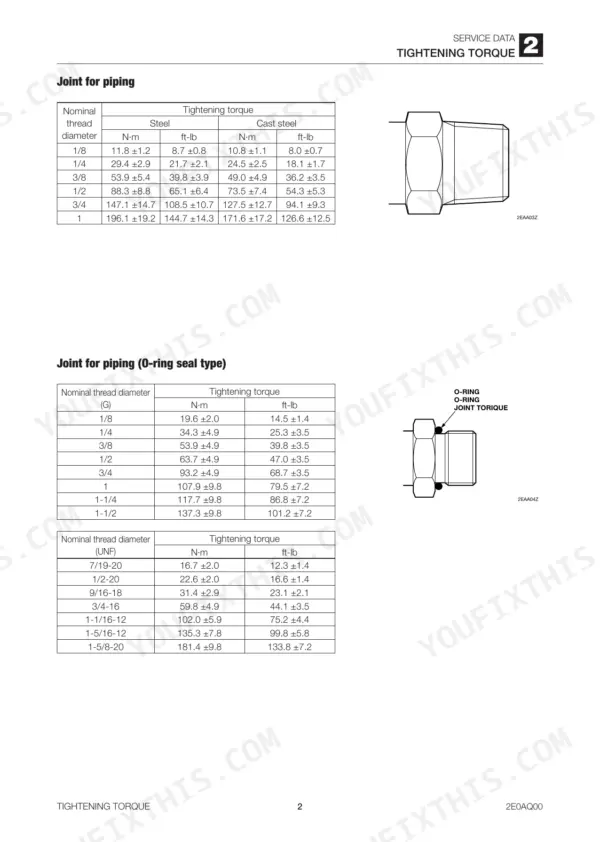
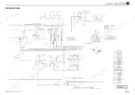
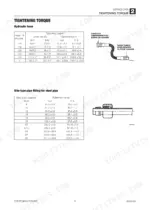
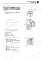
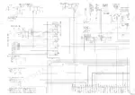
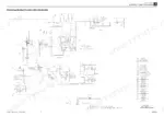
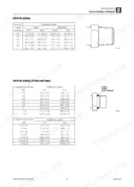
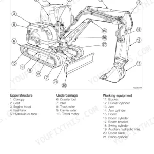
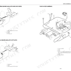
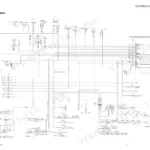
A TL12 that pulls to one side on a loaded push points straight at the drive circuit, and this 418-page Takeuchi TL12 service manual PDF (factory publication CU7E006) for the track loader is where your diagnosis starts. Hydraulic circuit diagrams trace oil through the control valve, standard and high flow, out to the lift arm and bucket cylinders, while wiring diagrams lay out the electrical circuits. Disassembly and assembly fills the biggest share of the book, covering the HST pump, drive system, frame and attachments, followed by troubleshooting sorted by traveling, lift arm and bucket faults, plus air conditioner service. Check charge pressure at 2.3 MPa low and 2.4 MPa high (334/363 psi), then confirm 34.5 MPa (5003 psi) on each forward travel circuit. A guessed relief setting can split a hose. Chapter bookmarks and a searchable text layer take you from the cover to the arm and bucket relief figures in two clicks.
What's Inside This Takeuchi TL12 Manual
| System | Pages | Key Topics |
|---|---|---|
| Safety | 3-12 | |
| Service Data | 13-79 | Specification Tables, Performance Criteria, Tightening Torque, Hydraulic Circuit Diagram |
| Function | 80-112 | Control Valve, Control Valve High Flow |
| Disassembly and Assembly | 113-129 | Service Standards, Drive System, Travel System |
| Frame | 130-164 | Operating Device, Attachments, Hydraulic Tank |
| HST Pump and Gear Pumps | 165-227 | HST Pump, Gear Pump, Gear Pump (High Flow), Test Operation |
| Control Valve | 228-254 | Control Valve (High-Flow), Sub Valve, Pilot Valve, Proportional Control Solenoid Valve |
| Cylinders | 255-269 | Piston Rod Assembly, Rod Cover, Special Tools, Inspection After Assembly |
| Travel Motor | 270-291 | Hydraulic Motor, Planetary Gear, Brake Piston, Floating Seals, Special Tools |
| Troubleshooting | 292-331 | Overall Machine, Traveling, Lift Arm, Bucket |
| Other | 332-418 | Air Conditioner, Air Conditioner System Red Dot, Maintenance Software Manual |
Quick Reference Specifications
| Specification | Value | Page |
|---|---|---|
| Track tension | 25 to 50 mm (1.0 to 2.0 in.) | p. 21 |
| Right travel (forward) pressure | 34.5 MPa (5003 psi) | p. 23 |
| Left travel (forward) pressure | 34.5 MPa (5003 psi) | p. 23 |
| Parking brake torque | 363 N·m (267.7 ft.-lb.) | p. 36 |
| Parking brake release pressure | 1.5 MPa (218 psi) | p. 36 |
| Track roller A Standard dimension | 216 mm (8.5 in.) | p. 114 |
| Track roller A Allowable value | 208 mm (8.2 in.) | p. 114 |
| Sprocket A Standard dimension | 410 mm (16.1 in.) | p. 114 |
| Sprocket A Allowable value | 402 mm (15.8 in.) | p. 114 |
| Idler A Standard dimension | 450 mm (17.7 in.) | p. 114 |
| Idler A Allowable value | 440 mm (17.3 in.) | p. 114 |
| Crawler belt weight | 255 kg (562 lb) | p. 127 |
Takeuchi TL12 Common Problems This Manual Covers
Takeuchi TL12 travel fails or veers to one side with high operating temperature
Test right and left travel (forward) pressure with a gauge and compare both sides against 34.5 MPa (5003 psi) listed on page 23. Check charge pressure against 2.3 MPa/2.4 MPa (334 psi/363 psi) low and high. If one side reads short, work through the Traveling and HST Pump charts starting on page 292.
Manual Section: Traveling p. 23Lift arm cylinder moves slow, lacks force, or does not move at all
Check the arm and bucket circuit pressure with a gauge against 20.6 MPa (2987 psi) shown on page 23. Verify the hydraulic tank level first; page 163 lists a 60 L (15.9 US gal.) level capacity. If pressure checks good, follow the Lift Arm and Control Valve charts starting on page 292.
Manual Section: Lift Arm p. 23Bucket cylinder drops spontaneously with oil leaking around the cylinder or control valve
Inspect the bucket cylinders for external oil leaks first, then check the control valve for oil leaks and spool sliding issues that let the actuator drop. Clean around fittings before you look so fresh seepage shows. Work through the Bucket, Cylinders and Control Valve charts in the Troubleshooting section starting on page 292.
Manual Section: Bucket p. 292Travel motor parking brake not releasing or holding, with 2nd-speed control acting up
Test parking brake release pressure at the travel motor against 1.5 MPa (218 psi) on page 36; the brake should hold 363 N·m (267.7 ft.-lb.) of torque. If the motor comes out, rig for 81 kg (179 lb) and torque the fixing bolts to 241 N·m (177.8 ft.-lb) per page 129.
Manual Section: Travel Motor p. 36Auxiliary hydraulics circuit not supplying the prescribed pressure when running a hydraulic attachment
Check sub valve solenoid operation and look for oil leaks at the sub valve and solenoid valve. Measure pilot pressure against 2.9 MPa (421 psi) on page 23 and check pilot valve secondary pressure. Trace the circuit on the hydraulic schematic before replacing parts.
Manual Section: Auxiliary Hydraulics p. 23Track rollers, idler and sprocket worn below allowable dimension during drive system inspection
Measure track roller A against 216 mm (8.5 in.) standard and 208 mm (8.2 in.) allowable, and idler A against 450 mm and 440 mm, per page 114. Replace worn parts, torque track roller A fixing bolts to 241 N·m (177.8 ft.-lb) per page 128, then set track tension to 25 to 50 mm on page 21.
Manual Section: Disassembly and Assembly p. 114Frequently Asked Questions
What are the replacement specifications for the bottom track rollers on a Takeuchi TL12?
The standard dimension for the track roller A is 216 mm (8.5 in.) and the allowable value is 208 mm (8.2 in.). For track roller B, the standard dimension is 328 mm (12.9 in.) and the allowable value is 320 mm (12.6 in.). p. 114
What is the tightening torque for the main relief valve on the Takeuchi TL12 control valve?
The tightening torque for the main relief valve on the control valve is 58.8 N·m to 68.6 N·m (43.4 ft.-lb to 50.6 ft.-lb). p. 89
What is the engine coolant capacity for the Takeuchi TL12?
The engine cooling system has a capacity of 16.5 L (17.4 US qt.). p. 19
What is the tightening torque for the gear pump cap screws on a Takeuchi TL12?
The cap screws on the gear pump should be tightened to 88.2 N·m to 93.1 N·m (65.1 ft.-lb to 68.7 ft.-lb). p. 75
How do I bleed air from the HST pump?
After installing the HST pump, fill the pump with oil through the plug hole (1) and pressure detection ports (M5) and (M15). Start the engine and run at idling speed for five minutes to bleed air out of the pump casing, then slowly operate the pilot valve to bleed the main and pilot circuits. p. 123
Will this Takeuchi TL12 Service Manual download right away?
A 418-page Service Manual in searchable PDF format, available the moment you complete checkout. View on computer, tablet, or phone, with no shipping wait.
Can I print specific sections of this Takeuchi TL12 Service Manual?
Yes. Print a single page or a chapter for your own shop use, on letter or A4.
Reviews
There are no reviews yet.