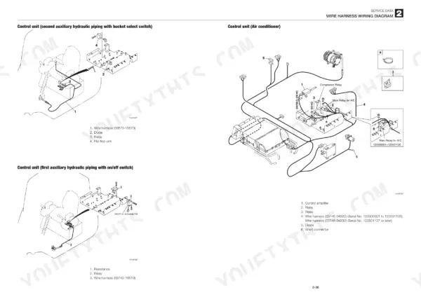
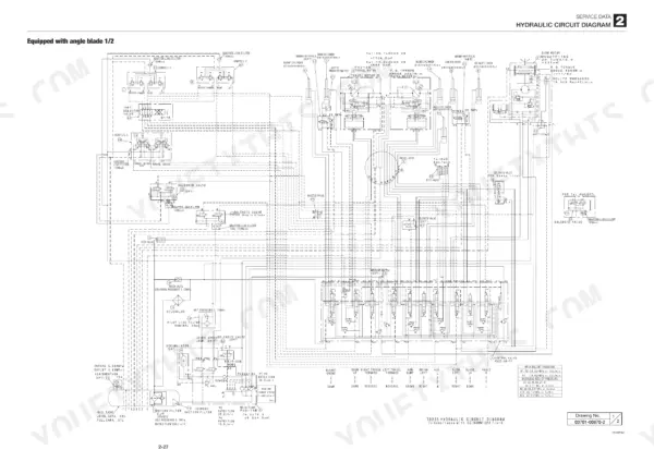
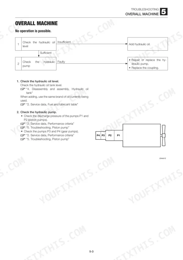
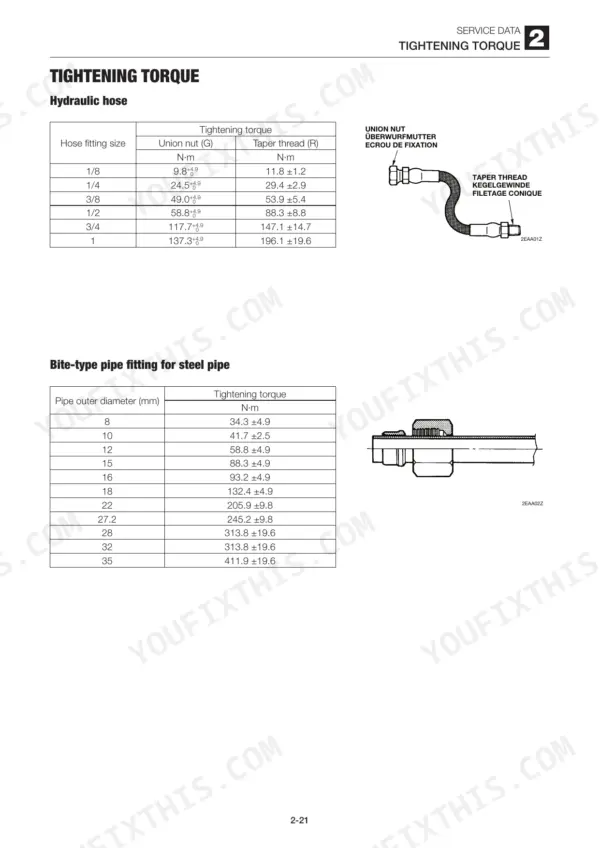
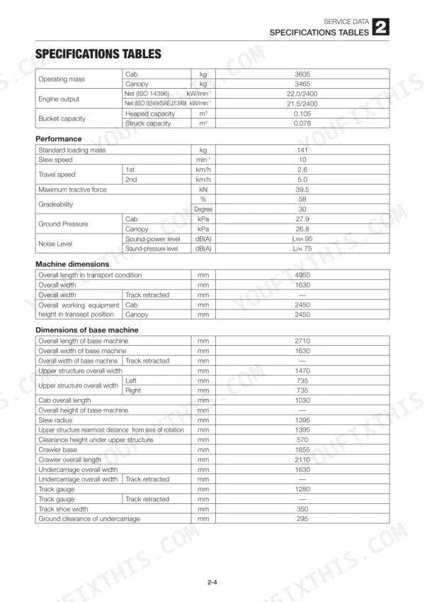
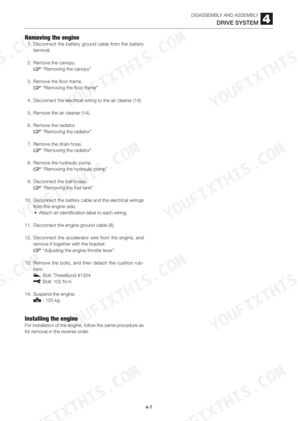
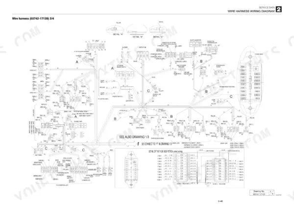
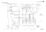
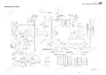
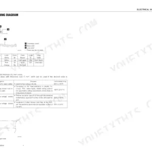
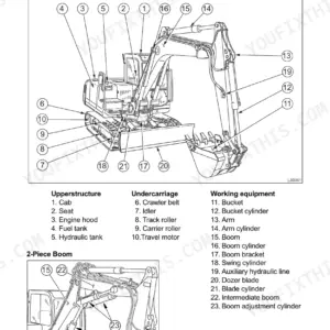
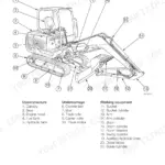
Written for one machine only, the Takeuchi TB235 mini excavator, this 326-page Takeuchi TB235 service manual PDF carries factory reference CG7E004. Hydraulic and electric circuit diagrams sit in the Service Data chapter beside the wire harness layout, so the pilot control circuit, main relief valve and solenoid valves can be traced from pump to actuator. Removal and installation work takes in the travel motor, crawler belts, slew bearing, swivel joint, boom, arm and dozer blade, while nearly a fifth of the book is given to troubleshooting sorted by travel, slew, boom, arm and bucket faults. Check carrier roller dimension A against the 76.3 mm standard and replace the roller once it wears to 72.3 mm; a 1/4 taper-thread hose fitting takes 29.4 ± 2.9 N·m. A slow slew rarely tells you which valve is at fault. Searchable text finds the procedure, bookmarks hold your place, and your TB235 is swinging and tracking again by the end of the shift.
What's Inside This Manual
| System | Pages | Key Topics |
|---|
| Safety | 3-12 | Safety Alert Symbol, Safety Precautions, Cautions When Working |
| Service Data | 13-72 | Dimensional Drawing, Specifications Tables, Lubricant and Fuel Chart, Performance Criteria, Tightening Torque, Hydraulic Circuit Diagram, Electric Circuit Diagram |
| Function | 73-96 | Piston Pump, Control Valve, Pilot Valve, Travel Motor, Slew Motor |
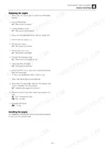
| Service Standards and Drive System | 97-109 | Service Standards, Engine Removal, Engine Installation, Throttle Lever Adjustment |
| Travel System | 110-114 | Crawler Belt Removal, Crawler Belt Installation, Carrier Roller, Track Roller, Travel Motor |
| Slew System | 115-117 | Slew Motor Removal, Slew Bearing, Swivel Joint |
| Upper Frame | 118-123 | Upper Frame Removal, Cover Removal, Cab Removal |
| Control System | 124-134 | Lever Stand, Control Lever, Pilot Valve, Control Cable Adjustment |
| Attachments | 135-140 | Bucket Removal, Arm Removal, Boom Removal, Swing Bracket, Dozer Blade |
| Hydraulic Components | 141-166 | Hydraulic Tank, Hydraulic Pump, Control Valve, Main Relief Valve, Port Relief Valve |
| Pilot Valves and Air Conditioner | 167-266 | Pilot Valve Construction, Auxiliary Pilot Valve, Travel Pilot Valve, Solenoid Valves, Air Conditioner |
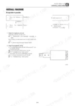
| Troubleshooting | 267-326 | Overall Machine, Traveling, Slewing, Boom, Arm, Bucket |
Quick Reference Specifications
| Specification | Value | Page |
|---|
| Check valve torque | 177 N·m | p. 110 |
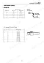
| Hydraulic hose Union nut (G) 1/8 | 9.8 +4.9 N·m | p. 33 |
| Hydraulic hose Taper thread (R) 1/8 | 11.8 ± 1.2 N·m | p. 33 |
| Carrier roller standard dimension A | 76.3 mm | p. 98 |
| Carrier roller allowable value A | 72.3 mm | p. 98 |
| Hydraulic oil tank capacity | 35 L | p. 142 |
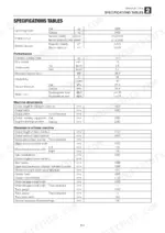
| Engine Oil Capacity (Upper limit) | 4.7 L | p. 21 |
| Hydraulic Tank Capacity | 35 L | p. 21 |
| Fuel Tank Capacity | 53 L | p. 22 |
| Main Relief Valve Pressure (Boom, Arm, Right/Left Travel) | 21.0 +1.4 MPa | p. 23 |
| Main Relief Valve Pressure (Dozer Blade, Slew) | 19.6 +2.0 MPa | p. 23 |
| Pilot Pressure | 3.9 ±0.3 MPa | p. 23 |