

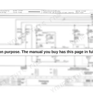
An hour from now you could have this 330-page Bomag BM 1000/30-2, BM 1200/30-2, BM 1300/30-2 Service Training PDF (OEM ID 008 919 42) open beside the machine, tracing a fault through the same wiring diagrams the factory techs work from; six BM cold milling machine variants are covered in one book, the three base models and their PB versions. The electrics chapter runs close to a quarter of the volume, mapping every control console on the operator's stand, terminal designations, and the flashing code table for engine diagnostic lamps H8 and H9. Full hydraulic and electric circuit diagrams close out the book, backed by troubleshooting tables for the axial piston pumps. Set the travel pump to its 410 to 430 bar maximum and hold the travel motors at 400 bar nominal, 450 bar top. When it is just you and a dead planer, this text-searchable, bookmarked file answers back. Download it and put the drum back in the cut.
Complete the set for your BM 1000/30-2 to 1300/30-2
What's Inside This Bomag BM 1000/30-2 to 1300/30-2 Manual
| System | Pages | Key Topics |
|---|---|---|
| General | 7-26 | Introduction, Safety Regulations, General Repair Instructions |
| Technical Data | 27-36 | Weights, Rotor, Travel Characteristics, Drive, Crawler Tracks, Electric System, Conveyor System, Filling Capacities |
| Maintenance | 37-40 | Fuels and Lubricants, Running-In Instructions |
| Electrics | 41-122 | Designation of Components in the Wiring Diagram, Terminal Designations in Wiring Diagram, Control Elements, Main Fuse, Fuses, Component Overview, View of Operator's Stand |
| Engine | 123-152 | Engine Attachment Parts, Engine Electrics, Checking the Cylinder Head Ground Cable, Engine Diagnostics Lamps, H8 and H9, Table of Flashing Codes, Check the Engine Oil Level |
| Milling Drive, Description | 153-162 | Power Transmission, Clutch, Oil Supply, Monitoring the Oil Pressure |
| Milling Unit, Description | 163-172 | Milling Drum Structure, Milling Housing, Tool Holders and Picks |
| Travel Drive, Description | 173-178 | Travel System |
| Conveyor Belt, Description | 179-184 | Conveyor Belts, Folding / Unfolding the Loading Conveyor Belt |
| Hydraulics | 185-224 | Hydraulic Circuit, Component Overview -- Hydraulics, Travel Pump, View of the Machine, Working Pump, Conveyor Belt Pump, Troubleshooting Axial Piston Pumps, Fan Pump |
| Hydraulics - Travel Circuit | 225-230 | Driving, Crawler System, Steering |
| Hydraulics - Milling Operation | 231-240 | Clutch, View of the Machine, Milling Box Hydraulics |
| Tests and Adjustments | 241-250 | Special Tools, Checking and Adjusting Travel Pump |
| Circuit Diagrams | 251-330 | Hydraulic Diagram, Electric Circuit Diagrams |
Quick Reference Specifications
| Specification | Value | Page |
|---|---|---|
| All Models | ||
| Travel motors Nominal pressure | 400 bar | p. 32 |
| Travel motors Top pressure | 450 bar | p. 32 |
| Travel pump Maximum pressure | 410 - 430 bar | p. 32 |
| Service pump Maximum pressure | 190 - 210 bar | p. 32 |
| Rated power ISO 3046 | 205 kW(HP) | p. 28 |
| Diesel fuel capacity | 500 l | p. 29 |
| Hydraulic oil capacity | 118 l | p. 29 |
| Water capacity | 1250 l | p. 29 |
| Tightening torque for counter nut (bypass) | 22 Nm | p. 195 |
| BM 1000/30 | ||
| Operating weight (Cece), BM 1000/30 | 19100 kg | p. 28 |
| BM 1200/30 | ||
| Operating weight (Cece), BM 1200/30 | 19400 kg | p. 30 |
| BM 1300/30 | ||
| Operating weight (Cece), BM 1300/30 | 19550 kg | p. 30 |
Bomag BM 1000/30-2 to 1300/30-2 Common Problems This Manual Covers
Bomag BM 1300/30-2 travel drive weak, machine barely creeps, crawler tracks stall under load
Check brake release pressure first; the brakes need at least 18 bar to release before the crawler tracks will move. Then tee a gauge into the travel circuit and run the pump pressure tests in the Tests and Adjustments section starting on page 241. If relief pressure will not reach 410 to 430 bar, suspect a worn travel pump.
Manual Section: Tests and Adjustments p. 241Milling drum won't turn or drum drive cuts out intermittently when lowered into the cut
Verify oil level in the hydraulic tank before condemning the drum drive; the system holds 118 l. Trace clutch engagement and drum circuit operation using the milling box hydraulics starting on page 231. Inspect the drive coupling for stripped splines and confirm the bypass counter nut is torqued to 22 Nm before retesting.
Manual Section: Hydraulics - Milling Operation p. 231Hydraulic pumps whining or growling, hydraulic oil overheating after a few hours of milling
Listen for cavitation whine at the axial piston pumps, then check suction lines for collapsed hoses and air leaks at the fittings. Confirm the tank is full; low oil in the 118 l system overheats fast. Test the service pump; if it cannot hold 190 to 210 bar, work through the pump troubleshooting in the Hydraulics section starting on page 185.
Manual Section: Hydraulics p. 185Engine down on power, runs hot, black smoke under load during full-depth passes
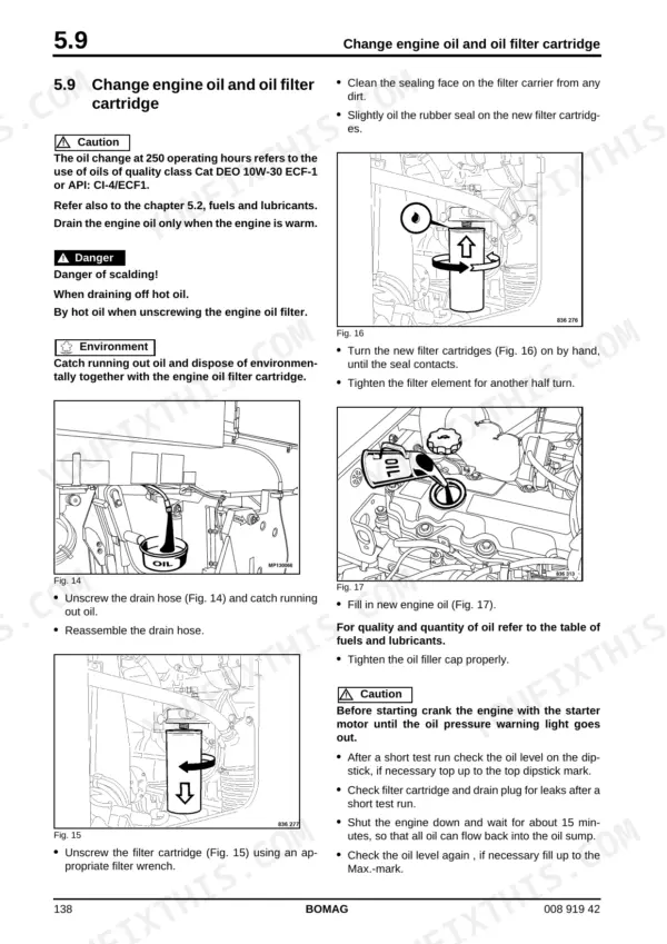
Drain the water separator and change the fuel filter following the engine service procedures on page 138. Check the air filter for dust loading and blow out the cooler cores. Press the V-belt between the pulleys; deflection beyond 10 to 15 mm means retension it (page 146). Keep engine oil on the 500 hour change interval.
Manual Section: Engine p. 138Loading conveyor belt runs slow or stalls, milled material backing up in the drum housing
Check conveyor circuit pressure before pulling the belt motor; maximum is 300 bar (page 33) with 210 bar nominal. Inspect belt tension and scrape packed millings off the rollers, then verify the conveyor belt pump reaches its 260 to 280 bar relief setting. Compare drive routing against the conveyor belt layout starting on page 179 to get material moving again this shift.
Manual Section: Conveyor Belt, Description p. 179Frequently Asked Questions
What is the procedure to reset the rear steering sensor to its neutral position?
After replacing the sensor, align the crawler tracks to the machine's longitudinal axis and center the sensor. With the ignition off, press buttons 14, 15, and 8 simultaneously, then switch the ignition on while keeping them depressed. Wait 30 seconds for stabilization, release the buttons, wait another 30 seconds, and press button 11 (DIS 0) to zeroize. p. 77
What is the tightening torque for an M12 metric thread screw, class 8.8, on the Bomag BM 1000/30-2 to 1300/30-2?
The tightening torque for an M12 metric unified thread screw with an 8.8 strength class is 88 Nm, assuming a coefficient of friction of 0.14. p. 23
What is the recommended engine oil change interval for the Bomag BM 1000/30-2 to 1300/30-2 cold milling machine?
The engine oil should be changed every 500 operating hours. If 500 hours are not reached within one year, the oil must be changed at least once per year. p. 38
What is the correct procedure for checking the V-belt tension on the generator system?
Inspect the V-belt for damage and use thumb pressure to check if it can be depressed by 10 to 15 mm between the pulleys. If it can be depressed more than this, the V-belt must be retightened. p. 146
What is the hydraulic oil tank filling capacity on the Bomag BM 1000/30-2 to 1300/30-2?
The hydraulic oil tank has a filling capacity of 118 liters. p. 29
What format is this Bomag BM 1000 manual in?
Delivery is instant: a 330-page searchable PDF is yours the second checkout clears. Laptop, tablet, or phone, all fine.
Can I print a copy of this Bomag BM 1000 Service Manual for the shop?
Yes. Many mechanics print the section they need for their own shop and bring it to the bench.
Reviews
There are no reviews yet.