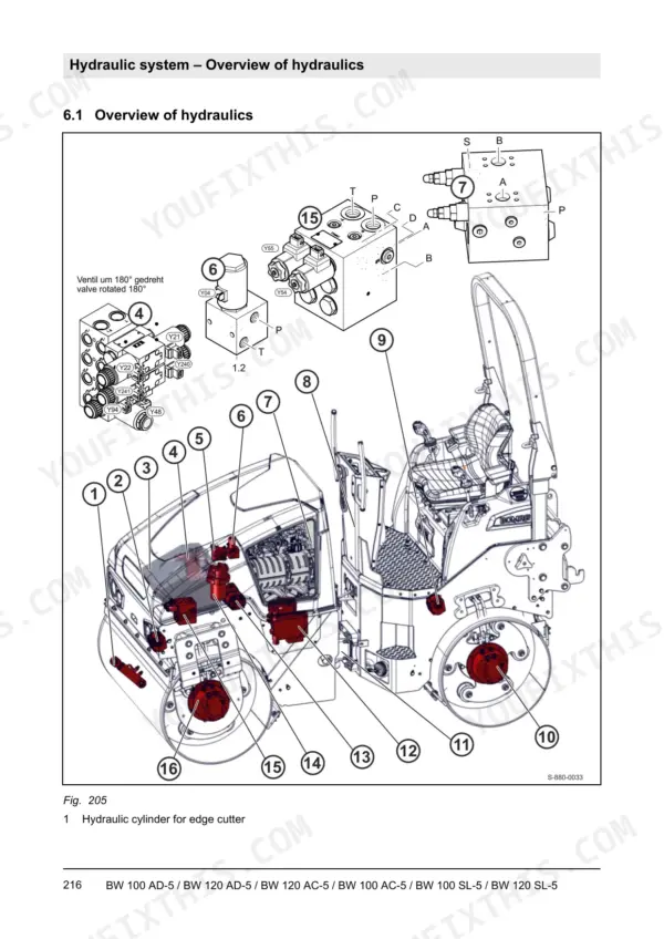
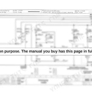
When the paving train is waiting on density and the roller shuts down mid-mat, this 822-page Bomag BW 120 SL-5 service manual PDF (OEM 008 401 24 EN) provides the factory data to get your BW 100 and 120 AD-5, AC-5, and SL-5 tandem vibratory rollers moving again. Detailed hydraulic schematics trace the closed-loop travel and vibration circuits so you can accurately diagnose pressure losses. The troubleshooting chapters cover the entire electrical system, including CAN bus networks and central electrics, backed by clear wiring diagrams to pinpoint sensor faults. During reassembly, secure the drum drive motor using a mounting torque of 211 Nm and confirm the main battery fuse is rated at 80 A. There is nothing worse than being alone with a dead machine and no one on the crew to ask for help, but buying this searchable, bookmarked file means the exact answers are yours to keep for the life of the roller.
Complete the set for your BW 100/120 AD-5, AC-5 and SL-5
Other edition of this manual
What's Inside This Manual
| System | Pages | Key Topics |
|---|
| General | 9-56 | Introduction |
| Technical Data | 57-86 | Bw 100 Ad-5 (Technical Data), Bw 100 AC-5 (Technical Data), Technical Data Bw 100 Sl-5 (Noise and Vibration Data), Bw 120 Ad-5 (Technical Data), Bw 120 AC-5 (Technical Data) |
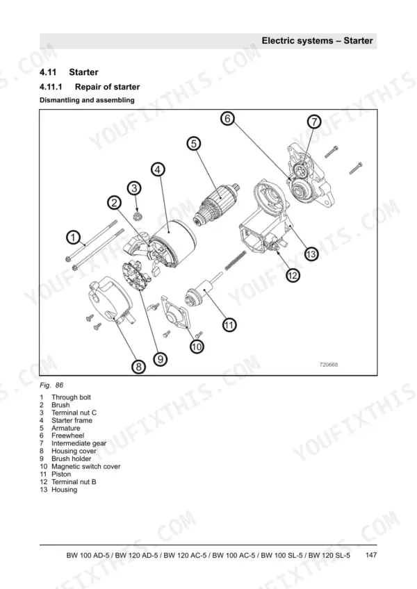
| Electric Systems | 103-176 | Overview of Electric System, Table of Fuels and Lubricants, Wiring, CAN Bus Overview, Central Electrics |
| Diesel Engine | 177-214 | Overview of Diesel Engine, Kubota Diesel Engine, Checking the Compression, Checking the Engine Oil Pressure, Checking the Thermostat in Disassembled State |
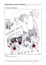
| Hydraulic System | 215-304 | Overview of Hydraulics, Open and Closed Hydraulic Circuit |
| Drum | 305-324 | Edge Cutter, Overview Drum, Removing and Installing the Drum, Dismantling the Drum, Assembling the Drum |
| Rubber Tires | 325-326 | Maintenance Work (Maintenance Table, Checks Prior to Start Up) |
| Scrapers | 327-330 | Maintenance Work (Scrapers, Checks Prior to Start Up) |
| Oscillating Articulated Joint | 331-340 | Overview Oscillating Articulated Joint, Disassembling the Oscillating Articulated Joint, Repairing the Oscillating Articulated Joint, Installing the Oscillating Articulated Joint |
| Troubleshooting | 341-394 | Preliminary Remarks |
| Disposal | 395-396 | Final Shut-Down of Machine |
| Special Tools | 397-402 | Electrics |
| Supplier Documentation: Travel Pump | 415-472 | Travel Pump Repair Instructions |
| Supplier Documentation: Drum Drive | 473-536 | Drum Drive Repair Instructions |
| Supplier Documentation: Wheel Drive | 537-753 | Wheel Drive Repair Instructions, General Repairs, Brake, Valving, Torque |
| Supplier Documentation: Steering Valve | 754-768 | Steering Valve Repair Instructions |
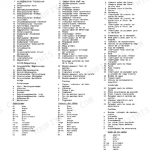
| Circuit Diagrams | 769-822 | Hydraulic Schematic, Electrical Wiring, CAN Bus, Fuse Assignment, Control Elements |
Quick Reference Specifications
| Specification | Value | Page |
|---|
| Drum drive motor mounting torque | 211 Nm | p. 97 |
| Main fuse | 80A | p. 109 |
| Main battery fuse | 80 A | p. 135 |
| Tightening torque for Telemecanique switch screw | 0.6 Nm | p. 171 |
| V-belt depression | 7 to 9 mm (0.28 – 0.35 inch) | p. 202 |
| Valve clearance (Intake / exhaust valve) | 0.18 mm to 0.22 mm (0.007 in to 0.009 in) | p. 206 |
| Maximum air pressure for cleaning | 2.1 bar (30 psi) | p. 212 |
| Engine Oil Capacity | 6.5L | p. 55 |
| Fuel Tank Capacity | 35L | p. 55 |
| Coolant Capacity | 6L | p. 55 |
| Hydraulic System Oil Capacity | 35L | p. 55 |
| Valve Clearance Intake | 0.18-0.22 mm | p. 84 |