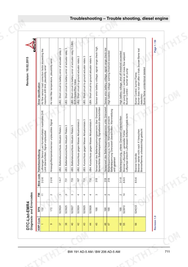
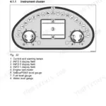
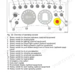
Restoring vibration control and travel performance to your tandem vibratory roller requires the Bomag BW 191 AD-5 AM, BW 206 AD-5 AM service manual PDF, delivering 914 pages of direct factory data (OEM 008 401 18 EN). The documentation maps out the complete electrical architecture with wiring diagrams for the Kubota and Deutz engines and the Asphalt Manager compaction system. Hydraulic schematics trace the closed-loop travel and vibration circuits, while troubleshooting charts guide you through faults like vibration loss on the front drum exciter. Verify your travel pump output by checking the forward and backward pressure test ports, which must hit exactly 450 bar, and ensure the charge pressure holds at 25 bar. A roller parked mid-mat costs the whole paving train time, so use the digital bookmarks to locate your Deutz EMR4 fault codes fast, print the pages you need, and take them straight to the drum.
What's Inside This Bomag BW 191 AD-5 AM, BW 206 AD-5 AM Manual
| System | Pages | Key Topics |
|---|
| General | 9-62 | Introduction |
| Technical Data | 63-86 | Bw 191 Ad-5 Am, Bw 206 Ad-5 Am, Additional Technical Data |
| Electric Systems | 109-342 | Basic Principles (Measuring Method, Understanding Electric Circuit Diagrams, Telemecanique Switch, Deutsch Plug, Series Dt and Dtm) |
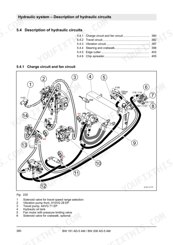
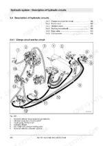
| Hydraulic System | 343-466 | Basic Principles (Open and Closed Hydraulic Circuit, Swash Plate Principle, Pump, Motor, External Gear Pumps, Outer Gear Motors Non-Reversible) |
| Machine Assemblies | 467-658 | Diesel Engine (Overview of Diesel Engine, Lubrication Oil Circuit Tcd 4.1 / 6.1, Coolant Circuit Tcd 4.1 / 6.1, Common Rail System, Wastegate Charge Pressure Controller, Exhaust Gas Recirculation, Eat – Exhaust Aftertreatment System, Engine Electrics, Maintenance Work) |
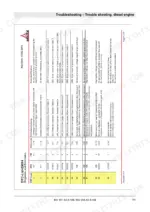
| Troubleshooting | 659-788 | Preliminary Remarks, Emergency Procedures (Actuating the Emergency Stop Switch, Disconnecting the Battery, Towing the Machine) |
| Special Tools | 789-794 | List of Special Tools, Electrics |
| Appendix | 813-914 | Circuit Diagrams (Circuit Diagram 485, Hydraulic Diagram 921 130 77, Water Spraying Diagram 921 133 28) |
Quick Reference Specifications
| Specification | Value | Page |
|---|
| Temperature sensor for hydraulic oil | 1K at 18°C | p. 164 |
| Solenoid valve resistance | 6 Ω | p. 356 |
| Charge pressure test port pressure | 25 bar | p. 356 |
| Solenoid valves resistance | 6 Ω | p. 411 |
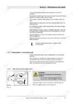
| Hydraulic oil filter replacement interval | 1000 operating hours | p. 462 |
| AdBlue/DEF filter cover tightening torque | 22.5 Nm (16.6 ft·lbf) | p. 539 |
| Fastening screw for idler pulley | 80 Nm (59 ft·lbf) | p. 549 |
| Maximum air pressure for cleaning air filter | 2.1 bar (30 psi) | p. 552 |
| Pressure switch low pressure off | 1.5 ±0.5 bar | p. 615 |
| Pressure switch low pressure on | 3.5 bar | p. 615 |
| Bending radius for GH 134 NW8 hose | 50 mm | p. 616 |
| Bending radius for GH 134 NW10 hose | 65 mm | p. 616 |